A micro heat pipe current assisted bending forming device and method
A technology of micro-heat pipe and winding, applied in the direction of forming tools, heat exchange equipment, manufacturing tools, etc., can solve the problem of heat transfer capacity decline, achieve the effect of improving production efficiency, high temperature, and reducing scale effect
- Summary
- Abstract
- Description
- Claims
- Application Information
AI Technical Summary
Problems solved by technology
Method used
Image
Examples
specific Embodiment approach 1
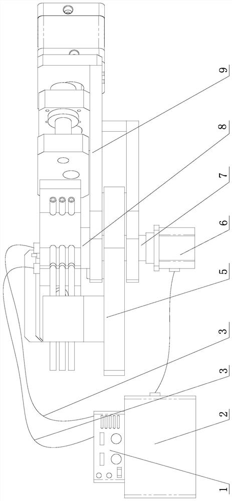
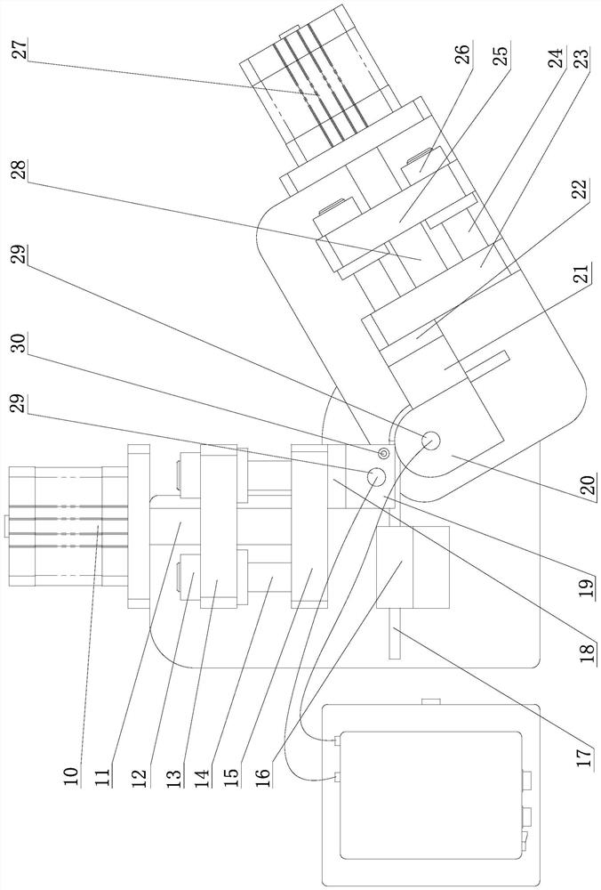
[0025] Specific implementation mode one: combine Figure 1 to Figure 2 Describe this embodiment, a micro heat pipe current-assisted bending forming device of this embodiment, including a bending forming machine, a mold assembly and an auxiliary forming power supply system, the mold assembly is installed on the bending forming machine, and the auxiliary forming power supply system is connected to the mold assembly or directly It is connected with the micro heat pipe blank 17 to provide high-density current to the micro heat pipe blank 17 during the forming process.
[0026] The winding forming machine described in this embodiment is mainly composed of a fixed base plate 5, a pressure pipe assembly, a pipe bending assembly, a rotating shaft 7, a rotating drive mechanism 6, and a control system 2; There is a rotating shaft 7, and the rotating shaft 7 cooperates with the shaft hole on the fixed base plate 5 to connect the elbow assembly and the fixed base plate 5 together, the pre...
specific Embodiment approach 2
[0029] Specific implementation mode two: combination Figure 1 to Figure 2 Describe this embodiment mode, the pressure tube assembly of a current-assisted bending forming device for micro heat pipes in this embodiment includes a pressure tube thrust mechanism 10, a pressure tube push rod 11, a pressure tube push plate 15, a pressure tube guide sleeve 12, a pressure tube guide Column 14 and pressure tube guide plate 13; pressure tube thrust mechanism 10 and pressure tube guide plate 13 are fixed on the fixed base plate 5, one end of pressure tube push rod 11 is connected with pressure tube thrust mechanism 10, and the other end passes through the pressure tube guide plate The via hole on the 13 is connected with the pressure tube push plate 15, and the pressure tube guide plate 13 is connected with the pressure tube push plate 15 by the pressure tube guide post 14 and the pressure tube guide sleeve 12. The pressure tube guide plate 13 guides the reciprocating translational moveme...
specific Embodiment approach 3
[0031] Specific implementation mode three: combination Figure 1 to Figure 2 Describe this embodiment, the elbow assembly of a current-assisted bending forming device for micro heat pipes in this embodiment includes an elbow thrust mechanism 27, an elbow push rod 28, an elbow push plate 23, a rotating base 9, and an elbow guide sleeve 26 , curved pipe guide post 24 and curved pipe guide plate 25; shaft hole is processed on the rotating base 9, and the rotating shaft 7 cooperates with the shaft hole and is fixed on the rotating base 9, and the curved pipe thrust mechanism 27 and the curved pipe guiding plate 25 are all Fixed on the rotating base 9, one end of the elbow push rod 28 is connected with the elbow thrust mechanism 27, and the other end passes through the hole on the elbow guide plate 25 to connect with the elbow push plate 23, and the elbow guide plate 25 passes through the elbow The guide post 24 and the elbow guide sleeve 26 are connected with the elbow push plate ...
PUM
| Property | Measurement | Unit |
|---|---|---|
| thickness | aaaaa | aaaaa |
Abstract
Description
Claims
Application Information
 - R&D
- Intellectual Property
- Life Sciences
- Materials
- Tech Scout
- Unparalleled Data Quality
- Higher Quality Content
- 60% Fewer Hallucinations
Browse by: Latest US Patents, China's latest patents, Technical Efficacy Thesaurus, Application Domain, Technology Topic, Popular Technical Reports.
© 2025 PatSnap. All rights reserved.Legal|Privacy policy|Modern Slavery Act Transparency Statement|Sitemap|About US| Contact US: help@patsnap.com


