


Quick Research
Generate reliable direction feasibility study reports for your R&D in just a few steps.

Technical Q&A
Discover and master advanced knowledge NOW. Basics, ideas, possibilities, all at once.

Find Solutions
As an expert in R&D theories, this can generate solutions to your technical problems instantly.

Evaluate Feasibility
Analyze your overall solution with one click, know your potential R&D risks in advance.

Monitor Landscape
Get weekly tech updates, stay abreast of the latest tech innovations and key insights.
An intelligent medical nursing bed
A technology of intelligent medical and nursing beds, which is applied in the fields of hospital beds, medical science, and hospital equipment. It can solve problems such as crowded registration areas, no seats in waiting areas, and inability to accommodate patients and caregivers at the same time, achieving high practicability and space. The effect of high utilization
- Summary
- Abstract
- Description
- Claims
- Application Information
AI Technical Summary
Problems solved by technology
Method used
Image


Examples
specific Embodiment approach 1
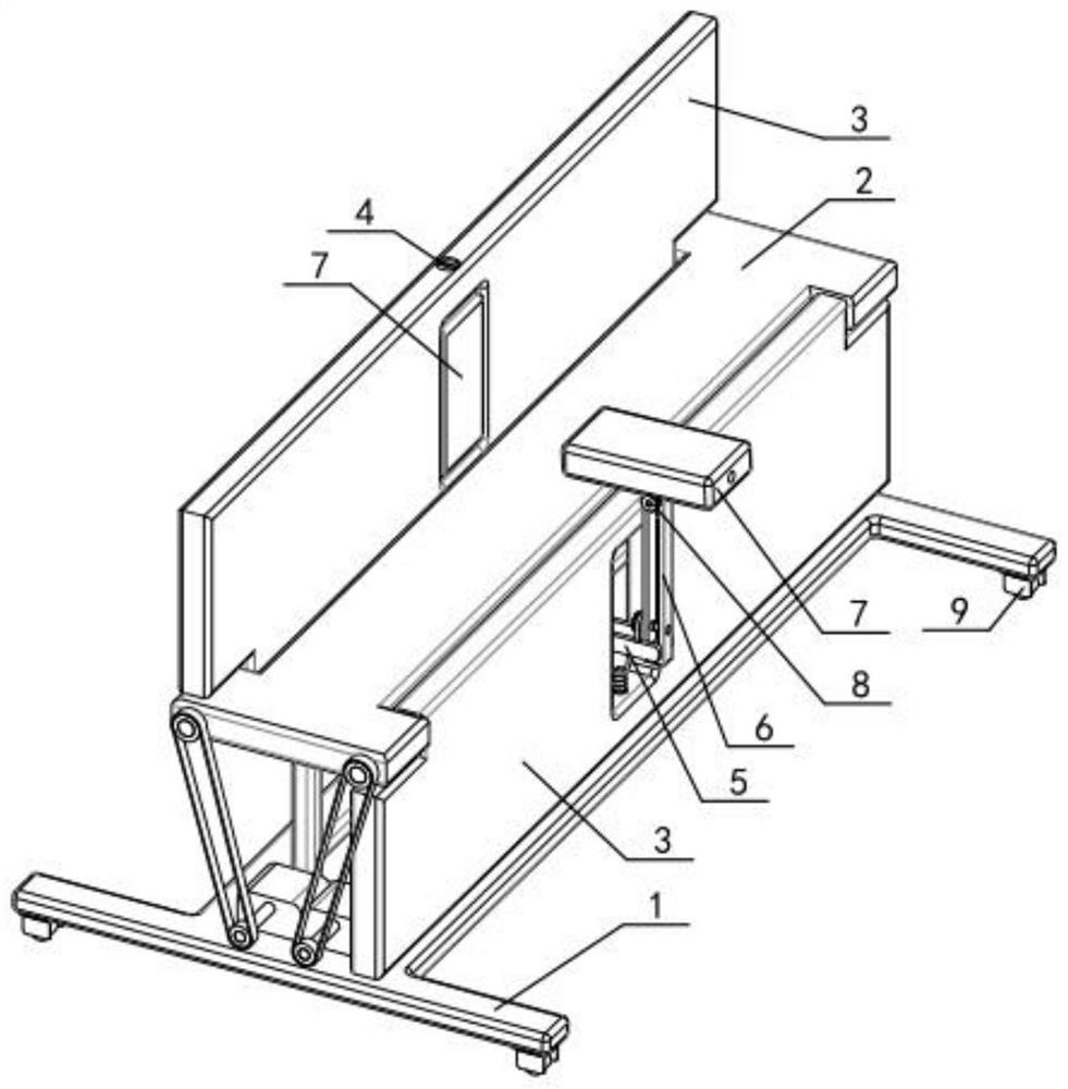
[0034] Such as Figure 1-13 As shown, an intelligent medical nursing bed includes an installation structure 1, a static part 2, a dynamic part 3, a cooperating pin 4, a displacement part 5, a main rod 6, a multifunctional part 7 and a pressure wheel 8, The upper end of the installation structure 1 is fixedly connected to the static part 2, and the left and right ends of the static part 2 are respectively connected to a dynamic part 3 by rotation, and a cooperating pin 4 is threaded on the two dynamic parts 3 respectively, and the installation structure 1 is connected with the inner ends of two displacement parts 5, the outer ends of the two displacement parts 5 are respectively connected with the lower end of a main rod 6, and the upper ends of the two main rods 6 are respectively connected with a multifunctional part 7, two The cooperating pin 4 is respectively connected with two multifunctional parts 7, and a pressure applying wheel 8 is threadedly connected to the two multi...
specific Embodiment approach 2
[0036] Such as Figure 1-13 As shown, the installation structure 1 includes a structure main body 1-1, a functional column 1-2, a bearing column 1-3, a motor 1-4 and a pulley I1-5, and the middle part of the structure main body 1-1 The left and right sides are respectively fixedly connected to a functional column 1-2, and a plurality of through holes are respectively arranged on the two functional columns 1-2, and the front and rear ends of the structure main body 1-1 are respectively fixedly connected to two load-bearing columns 1-3, and the structure The rear end of the main body 1-1 is fixedly connected with two motors 1-4, and the output shafts of the two motors 1-4 are respectively fixedly connected with a pulley I1-5. Structure body 1-1 such as Figure 5 As shown, its front and rear ends should have sufficient length to maintain the stability of the present invention, and there should be a certain space at the left and right ends, so that when the present invention beco...
specific Embodiment approach 3
[0038] Such as Figure 1-13 As shown, the static position part 2 includes a static position part body 2-1, a concave part 2-2, a shaft 2-3 and a pulley II 2-4, and the left and right ends of the static position part body 2-1 are respectively arranged A concave part 2-2, the left and right ends of the static part body 2-1 are respectively rotated and connected to a shaft 2-3, and the rear ends of the two shafts 2-3 are respectively fixedly connected to a pulley II 2-4; The lower end of the main body 2-1 is fixedly connected to two functional columns 1-2 and four bearing columns 1-3, and the two pulleys II 2-4 are respectively connected to the two pulleys I 1-5 through belt transmission. The width of static position portion body 2-1 preferably should be 25-30 centimeters, and purpose is to be convenient to the present invention when being adjusted into seat state, is convenient to the user sits on static position portion body 2-1, and recessed portion 2-2 and The combination of...
PUM
 Abstract
Description
Claims
Application Information
 - R&D Engineer
- R&D Manager
- IP Professional
- Industry Leading Data Capabilities
- Powerful AI technology
- Patent DNA Extraction
Browse by: Latest US Patents, China's latest patents, Technical Efficacy Thesaurus, Application Domain, Technology Topic, Popular Technical Reports.
© 2024 PatSnap. All rights reserved.Legal|Privacy policy|Modern Slavery Act Transparency Statement|Sitemap|About US| Contact US: help@patsnap.com