
High beam and dipped beam graded identification device and automobile high beam headlight abuse mobile evidence obtaining device

A technology of high and low beams and devices, which is applied in the direction of instruments, electrical components, traffic flow detection, etc., can solve the problems of high beam identification and classification, inappropriate use of high beams, illegal use of high beams, etc., to ensure measurement accuracy Effect

Pending Publication Date: 2019-07-12
姜与时
View PDF0 Cites 0 Cited by
  • Summary
  • Abstract
  • Description
  • Claims
  • Application Information

AI Technical Summary

Problems solved by technology

[0005] 1. When meeting vehicles on a road without central isolation facilities or without a central line, high beams cannot be used within 150 meters from vehicles coming from the opposite direction;
[0006] 2. High beams cannot be used when there is no central isolation facility or a narrow bridge or narrow road without a central line meets non-motorized vehicles;
[0007] 3. When passing through an intersection controlled by traffic signals, high beams cannot be used when turning;
[0008] 4. When a motor vehicle is driving at night without street lights, with poor lighting, or in conditions of low visibility such as fog, rain, snow, sand, etc., when the vehicle behind and the vehicle in front are driving in the same direction at close distances, high beams cannot be used;
[0010] 6. High beams should not be used in well-lit urban areas
[0011] Although the "Road Traffic Safety Law" clearly stipulates several situations in which high beams cannot be used when driving at night, there are always drivers who illegally use high beams at night, causing serious traffic accidents
Many automobile manufacturers, inventors, and traffic management departments have proposed technical solutions to solve the illegal use of high beams when driving at night. However, it is a difficult problem to identify and classify high beams in these technical solutions.

Method used


Image

  • High beam and dipped beam graded identification device and automobile high beam headlight abuse mobile evidence obtaining device
  • High beam and dipped beam graded identification device and automobile high beam headlight abuse mobile evidence obtaining device
  • High beam and dipped beam graded identification device and automobile high beam headlight abuse mobile evidence obtaining device

Examples


Embodiment 1

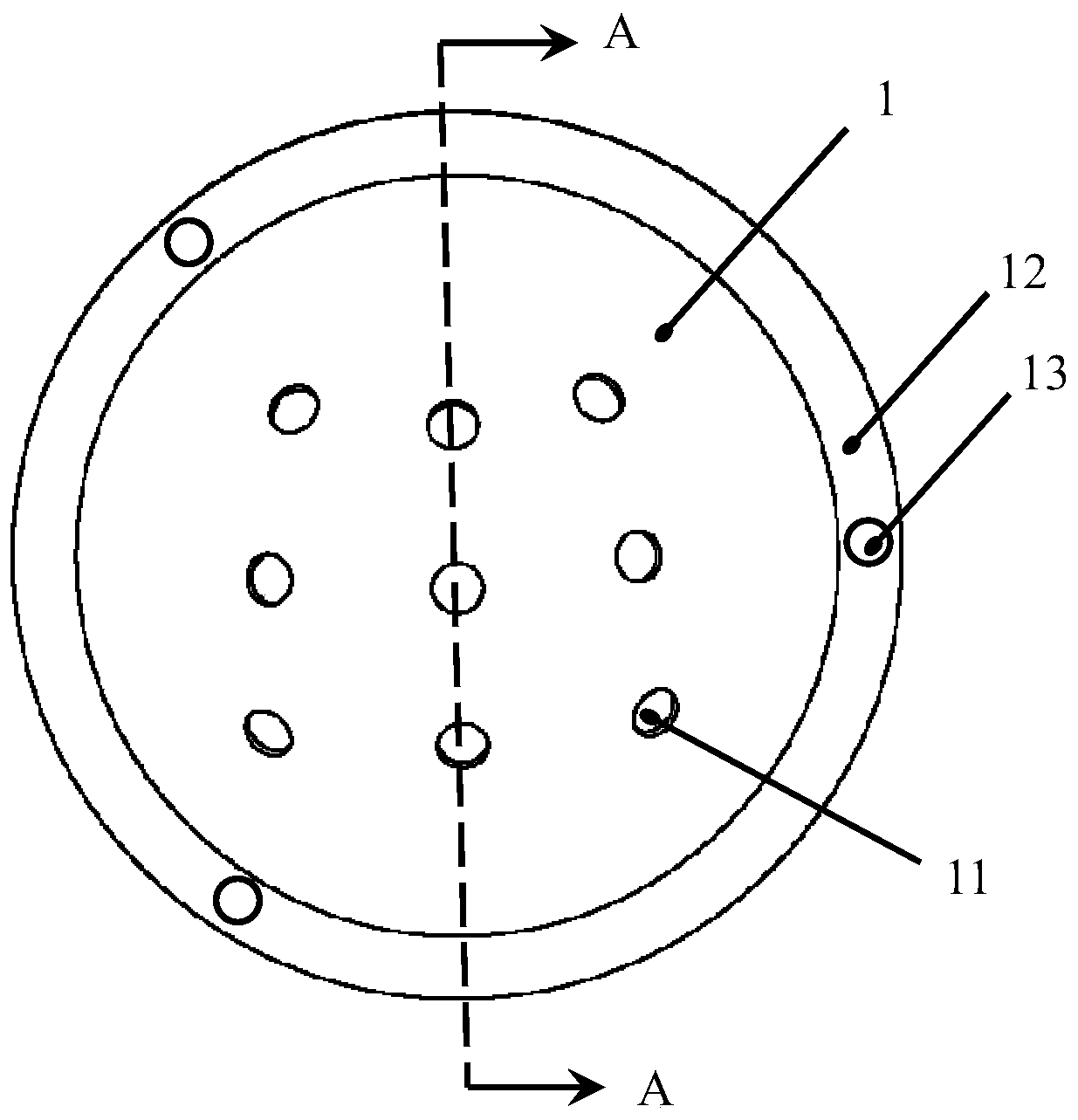
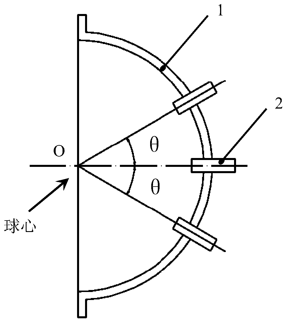
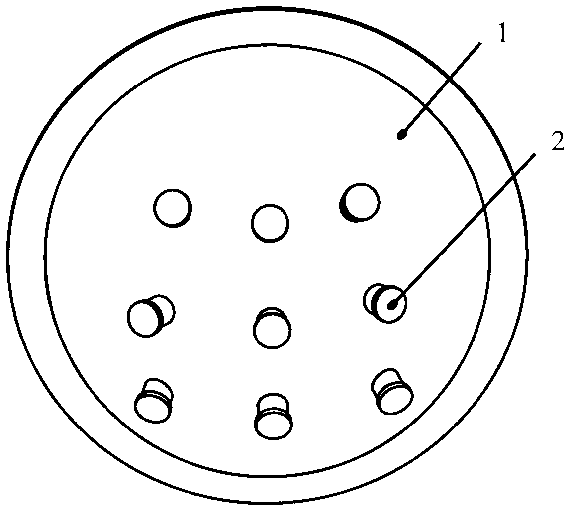
[0039] A hemispherical far and near light classification identification device, comprising a hemispherical cover 1, processing a plurality of mounting holes 11 arranged in a matrix on the hemispherical cover 1, characterized in that it also includes N light identification units 2, and the The light identification units 2 are installed in the installation holes 11 of the dome cover 1 so that the central axis of each light identification unit 2 points to the center of the dome cover 1 .

[0040] see figure 1 , is a schematic structural diagram of a hemispherical cover of a hemispherical far and near light classification recognition device provided by an embodiment of the present disclosure. The diameter of the dome cover is 150 mm, and the width of the flange side is 20 mm. Nine mounting holes 11 are processed on it, arranged in a matrix, with 3 rows and 3 columns.

[0041] see figure 2 , is a cross-sectional view of a hemispherical cover of a hemispherical far and near light...

Embodiment 2

[0067] The principle in this embodiment is the same as that in Embodiment 1, except that mounting holes 11 arranged in a 4×4 matrix are processed on the dome cover 1 to install 16 collimators 21 .

[0068] The advantage is that it can more accurately identify and classify the far and near beams of the car.

Embodiment 3

[0070] This embodiment discloses the technical details of a mobile vehicle evidence collection device for high beam abuse of motor vehicles.

[0071] A mobile evidence collection device for the abuse of high beam lights of motor vehicles, including a housing, a storage unit, an imaging unit, a communication unit and a microcontroller unit, the storage unit, the imaging unit, the communication unit and the microcontroller The electrical connection of the unit is characterized in that it also includes a hemispherical far and near light classification identification device, the hemispherical cover of the hemispherical far and near light classification identification device is connected with the housing bolts, and the hemispherical far and near light classification identification device The light recognition unit is electrically connected with the microcontroller unit.

[0072] see Figure 8 , is a schematic structural diagram of a mobile vehicle evidence collection device for hi...


PUM

PropertyMeasurementUnit
Diameteraaaaaaaaaa

Abstract

The invention discloses a hemisphere type high beam and dipped beam graded identification device, belonging to the field of mechanical-electrical integration. The hemisphere type high beam and dippedbeam graded identification device comprises a hemisphere cover, wherein a plurality of mounting holes arranged in matrix form are processed on the hemisphere cover, and the hemisphere type high beam and dipped beam graded identification device is characterized by further comprising N light identification units (N is greater than or equal to 3), the light identification units are mounted in the mounting holes of the hemisphere cover, and a central axis of each light identification unit is enabled to point to a center of sphere. According to the hemisphere type high beam and dipped beam graded identification device provided by the invention, the light identification units are arranged in matrix form on the hemisphere cover, a vertical included angle of the mounting holes is theta while a horizontal included angle is phi; and according to the hemisphere type high beam and dipped beam graded identification device provided by the invention, the light identification units are cylindrical, thus, an incident light is guaranteed to be a parallel light, and measurement accuracy of an incident light angle is guaranteed; and the invention also discloses an automobile high beam headlight abusemobile evidence obtaining device.

Description

technical field [0001] The invention discloses a hemispherical far and near light classification recognition device, which belongs to the field of electromechanical integration. At the same time, a mobile vehicle evidence collection device for high beam abuse of motor vehicles is disclosed. Background technique [0002] At present, the abuse of high beams is a traffic habit and road killer that is difficult to cure. According to statistics, the traffic accident rate at night is 1.5 times higher than that during the day, and more than 60% of major traffic fatal accidents occur at night. Relevant data from the Ministry of Public Security also show that 30%-40% of car accidents at night are caused by the abuse of high beams, and it is on the rise. In Baidu, when searching for the keyword "abuse of high beams", there are more than 700,000 content related to the abuse of high beams. This shows that the abuse of high beams has become one of the important hidden dangers of road ...

Claims


Application Information

Patent Timeline
IPC IPC(8): G08G1/017G08G1/04H04N5/225
CPCG08G1/0175G08G1/04H04N23/57
Inventor 姜与时
Owner 姜与时
Learn More