A method and device for obtaining aerosol extinction coefficient

A technology of extinction coefficient and aerosol, which is applied in the direction of measuring devices, climate sustainability, particle and sedimentation analysis, etc., and can solve problems with large limitations and difficulty in achieving high precision

Active Publication Date: 2021-08-31
北京是卓科技有限公司
View PDF13 Cites 0 Cited by
  • Summary
  • Abstract
  • Description
  • Claims
  • Application Information

AI Technical Summary

Problems solved by technology

[0007] 1) The slope method assumes that the atmosphere is a uniform atmosphere as a condition, but this kind of weather is difficult to occur in actual situations, so this method is difficult to achieve high accuracy, and can only be used in the horizontal direction
[0008] 2) The Klett method only considers a single component, that is, it can only be used when the aerosol concentration is large, and it is assumed that the relationship between the reflection and extinction coefficients satisfies β=B·α k , so this method can only be used in high-concentration weather, which has great limitations
[0009] 3) The Fernald method assumes that the scattering coefficient and extinction coefficient of particles at a certain height (about 5KM) are close to a fixed value, and that the ratio of the atmospheric extinction coefficient to the backscattering coefficient is 8π / 3, but the actual situation may not meet the above conditions, and this method can only be used in the vertical direction

Method used


Image

  • A method and device for obtaining aerosol extinction coefficient
  • A method and device for obtaining aerosol extinction coefficient
  • A method and device for obtaining aerosol extinction coefficient

Examples


specific Embodiment 1

[0104] Specific embodiment one (the 2nd identification point is measuring point),

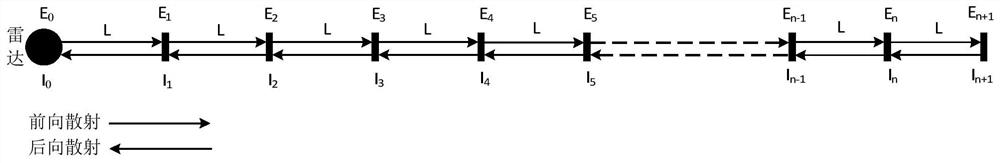
[0105]First, take the position where the lidar is located as the origin, and set n+1 equidistant marker points on the detection path of the lidar (such as figure 2 shown), and take the second mark point on the detection path starting from the origin as the measurement point. In addition, as an optional embodiment, the distance L between two adjacent marking points is 15 meters (m).

[0106] The aerosol extinction coefficient α at the measurement point is obtained by measuring the atmospheric integral turbidimeter at the second mark point 2 and the backscatter coefficient β 2 , and calculate the atmospheric correction parameter A. For example, as an optional embodiment, α 2 =1*10 -5 , β 2 =2*10 -6 , A=1.

[0107] Use the laser radar to launch the laser pulse into the atmosphere along the detection path, and measure the intensity I of the backscattered light at each mark point on the det...

specific Embodiment 2

[0118] Specific embodiment two (the nth marking point is a measuring point),

[0119] First, take the position where the lidar is located as the origin, and set n+1 equidistant marker points on the detection path of the lidar (such as figure 2 shown), and take the nth mark point on the detection path starting from the origin as the measurement point. In addition, as an optional embodiment, the distance L between two adjacent marking points is 15 meters (m).

[0120] The aerosol extinction coefficient α at the measurement point is obtained by measuring the atmospheric integral turbidimeter at the nth mark point n and the backscatter coefficient β n , and calculate the atmospheric correction parameter A. For example, as an optional embodiment, α n =1.5*10 -5 , β n =2.3*10 -6 , A=1.1.

[0121] Use the laser radar to launch the laser pulse into the atmosphere along the detection path, and measure the intensity I of the backscattered light at each mark point on the detecti...


PUM


Abstract

The present invention provides a method and device for obtaining the aerosol extinction coefficient, wherein the method includes: setting a plurality of equidistant marker points on the detection path of the laser radar, and using at least one marker point as a measurement point; At the point, the aerosol extinction coefficient and backscattering coefficient are measured by an atmospheric integral turbidimeter; according to the aerosol extinction coefficient and backscattering coefficient at the measurement point, and the relationship between the aerosol extinction coefficient and the backscattering coefficient, calculate Obtain the atmospheric correction parameters; use the laser radar to launch the laser pulse into the atmosphere along the detection path, and measure the intensity of the backscattered light at each marked point; according to the aerosol extinction coefficient, backscattering coefficient, aerosol The relationship between the extinction coefficient and the backscattering coefficient, and the intensity of the backscattered light at each marked point are calculated to obtain the aerosol extinction coefficient at each marked point. The application of the invention can accurately calculate the aerosol extinction coefficient.

Description

technical field [0001] The present application relates to the technical field of lidar, and in particular to a method and device for obtaining an aerosol extinction coefficient. Background technique [0002] With the aggravation of industrial pollution, smog weather occurs frequently, and air pollution has seriously affected human health. Therefore, the detection of air quality has become particularly important, and the monitoring, analysis and research of particulate matter in the air has become the focus of current environmental protection work. [0003] According to the aerodynamic diameter, atmospheric particulate matter can be divided into: (1) total suspended particulate matter (TSP for short) with a diameter of less than 100 microns; (2) inhalable particulate matter with a diameter of less than 10 microns; fine particles. Among them, fine particulate matter PM2.5 can be suspended in the atmosphere for a long time, which has an important impact on air quality and vis...

Claims


Application Information

Patent Timeline
Patent Type & Authority Patents(China)
IPC IPC(8): G01N21/47G01S17/95G01N15/06G01N15/02
CPCG01N15/02G01N15/0211G01N15/06G01N21/47G01N2015/0693G01S17/95Y02A90/10
Inventor 张景秀张志伟侯珑斐
Owner 北京是卓科技有限公司
Why Eureka
Try Eureka