
Gate opening degree sensor

A gate opening and sensor technology, applied in the field of gate sensors, can solve problems such as inconvenient operation, affecting service life, easy to appear corrosion, etc., and achieve the effect of simple installation method, convenient installation and disassembly, and not easy to corrode

Pending Publication Date: 2019-07-12
ANHUI UNIV OF SCI & TECH GUOZHEN INFORMATION TECH CO LTD
View PDF1 Cites 4 Cited by
  • Summary
  • Abstract
  • Description
  • Claims
  • Application Information

AI Technical Summary

Problems solved by technology

[0004] The object of the present invention is to provide a gate opening sensor to solve the problem that the existing gate opening sensor proposed in the above background technology is not convenient to operate, and the distance from the water surface is relatively low, and it is prone to corrosion, which affects its use. The problem of longevity

Method used


Image

  • Gate opening degree sensor
  • Gate opening degree sensor
  • Gate opening degree sensor

Examples


Embodiment 1

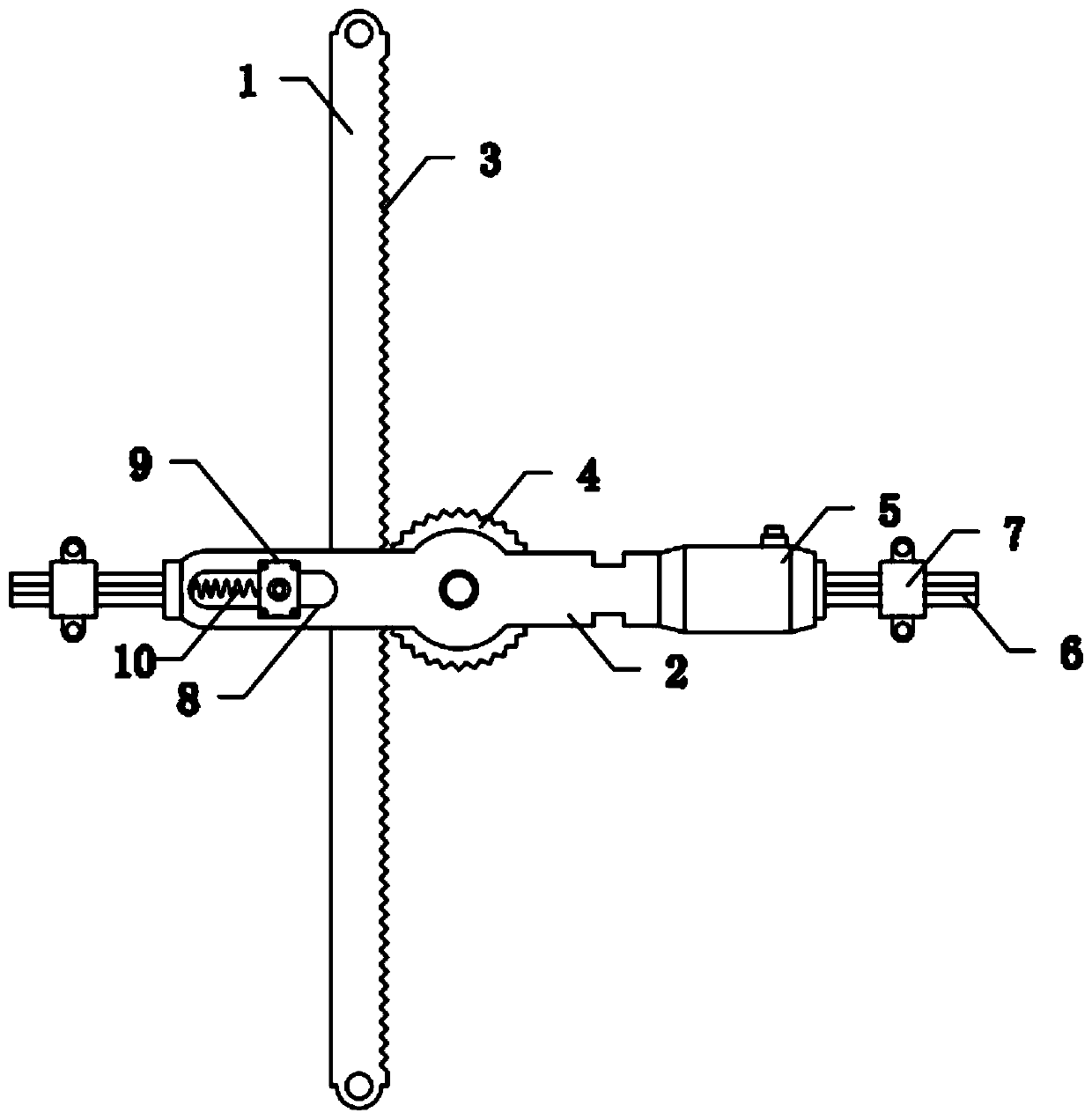
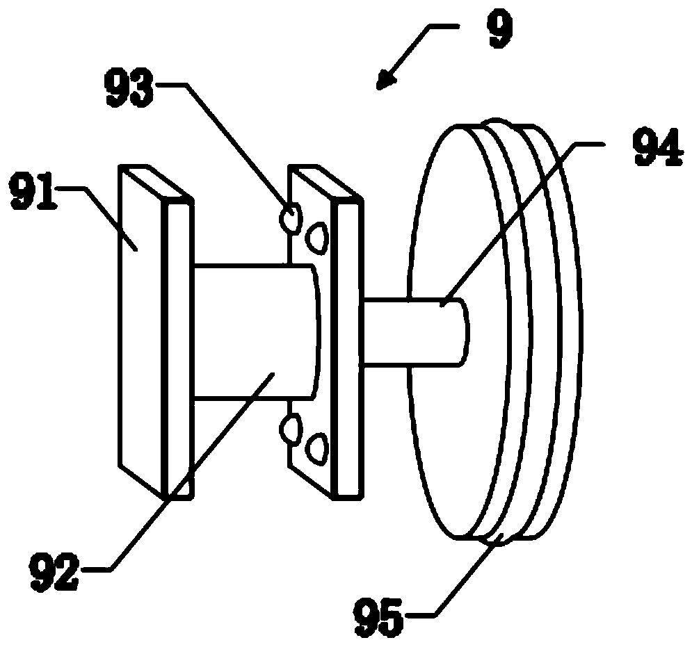
[0027] see Figure 1-3 , the present invention provides a technical solution: a gate opening sensor, including a limit rod 1 and a mounting bracket 2, a rack 3 is arranged on one side wall of the limit rod 1, and a rack 3 is connected to the mounting bracket 2 through a pin shaft. The detection gear 4, the detection gear 4 is meshed with the rack 3, and one end of the mounting bracket 2 is fixedly screwed with a speed sensor 5, the speed sensor 5 and the detection gear 4 are installed on the same side, and the detection end of the speed sensor 5 faces the detection gear 4;

[0028] The teeth of the detection gear 4 are provided with light guide sheets and light-shielding sheets, and the light guide sheets and light-shield sheets are arranged alternately. The light guide sheets and light-shield sheets are respectively arranged on the tooth peaks and tooth valleys of the detection gear 4 teeth. The modulus range of 4 is 1.5-2, and the rotational speed sensor 5 is a photoelectric...

Embodiment 2

[0029] Embodiment 2: A gate opening sensor, including a limit rod 1 and a mounting bracket 2, a rack 3 is arranged on a side wall of the limit rod 1, and a detection gear 4 is connected to the mounting bracket 2 through a pin shaft to detect The gear 4 is meshed with the rack 3, and one end of the mounting bracket 2 is fixedly screwed with a speed sensor 5, and the speed sensor 5 and the detection gear 4 are installed on the same side, and the detection end of the speed sensor 5 faces the detection gear 4;

[0030] The teeth of the detection gear 4 are provided with light guide sheets and light-shielding sheets, and the light guide sheets and light-shield sheets are arranged alternately. The light guide sheets and light-shield sheets are respectively arranged on the tooth peaks and tooth valleys of the detection gear 4 teeth. The modulus range of 4 is 1.5-2, and the rotational speed sensor 5 is a photoelectric sensor.

[0031] Wherein, the axis of the rotation speed sensor 5 a...


PUM


Abstract

The invention belongs to the technical field of gate sensors, and specifically discloses a gate opening degree sensor, which comprises a limiting rod and a mounting bracket, a rack is arranged on oneside wall of the limiting rod, the mounting bracket is connected witha detection gear through a pin shaft, and the detection gear and the rack are coupled; one end of the mounting bracket is fixedly connected with a rotation speed sensor in a threaded mode, the rotation speed sensor and the detection gear aremounted on the same side, the detection end of the rotation speed sensor faces towards thedetection gear,the detection gear rotates through the meshing action between the rack and the detecting gear, thus the detecting basis of the rotating speed sensor is provided, the detection is convenient, the installation method is simple, and water erosion is unlikely; by using the rotation speed sensor and the detection gear cooperatively, data detection is relatively accurate; and through theinstallation method of the mounting bracket and the rotation speed sensor, installation and disassembling are convenient, and subsequent maintenance is more convenient.

Description

technical field [0001] The invention relates to the technical field of gate sensors, in particular to a gate opening sensor. Background technique [0002] The sluice is a low-head hydraulic structure built on the banks of rivers, channels, reservoirs, and lakes, and has the functions of retaining and releasing water. Closing the gates can block floods, block tides, and raise water levels to meet the needs of upstream water intake or navigation; opening gates can discharge floods, drain water, flush sand, draw water, or adjust flow according to downstream water needs. By controlling the opening scale of the sluice gate, the water discharge and storage capacity of the sluice can be strictly controlled. [0003] For example, Chinese Patent Publication No. CN107289853A provides an underwater gate opening sensor, including a housing, a stator fixed in the housing, a rotor located in the housing, continuous windings, several sine windings, and several cosine windings; the rotor i...

Claims


Application Information

Patent Timeline
Patent Type & Authority Applications(China)
IPC IPC(8): G01B7/30G01P3/48
CPCG01B7/30G01P3/48
Inventor 李伟陈志华徐四清王富海
Owner ANHUI UNIV OF SCI & TECH GUOZHEN INFORMATION TECH CO LTD
Learn More