Eureka AIR delivers breakthrough ideas for toughest innovation challenges, trusted by R&D personnel around the world.

Roller kiln cooling device

A technology of cooling device and roller kiln, which is applied to furnace types, furnaces, lighting and heating equipment, etc., can solve the problems of bad influence of the working environment of employees, increase the burden of employees, reduce output, etc., and improve the working environment and labor intensity of employees. , the effect of reducing the rapid cooling time and reducing the firing cycle

Pending Publication Date: 2019-07-12
DONGGUAN CITY WONDERFUL CERAMICS IND PARK +2
View PDF0 Cites 1 Cited by
  • Summary
  • Abstract
  • Description
  • Claims
  • Application Information

AI Technical Summary

Problems solved by technology

However, the cooling efficiency of the axial flow fan is slow, so the fast cooling section of the existing roller kiln is relatively long, which increases the manufacturing cost of the kiln and the production cycle of the product; the life of the axial flow fan is relatively short, and failures often occur during the production process. The production is unfavorable, and it also adds a lot of burden to the employees; and from the environmental point of view, multiple axial flow fans operate at the same time, which will generate a lot of noise, which will have a bad impact on the working environment of the employees
Therefore, the effect of the axial flow fan in the roller kiln is not good, the cooling efficiency of the axial flow fan is slow, resulting in low cooling efficiency, the distance of the fast cooling section of the roller kiln is lengthened, resulting in a long firing cycle, which reduces the output

Method used


Image

  • Roller kiln cooling device
  • Roller kiln cooling device
  • Roller kiln cooling device

Examples


Embodiment Construction

[0026] In order to make the object, technical solution and advantages of the present invention more clear and definite, the present invention will be further described in detail below with reference to the accompanying drawings and examples. It should be understood that the specific embodiments described here are only used to explain the present invention, not to limit the present invention.

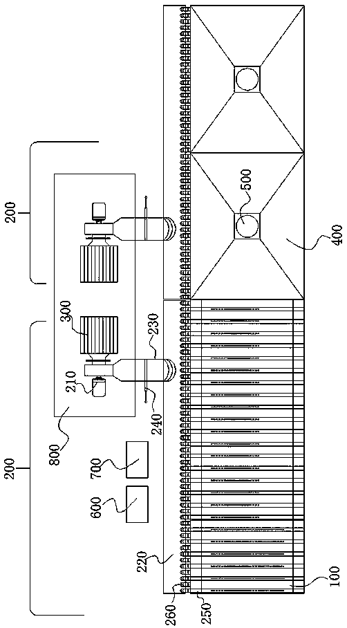
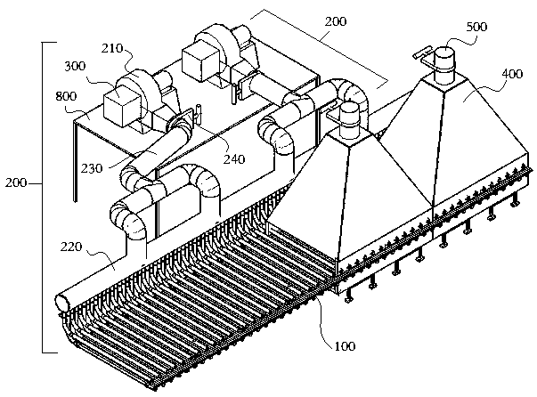
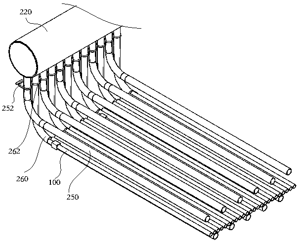
[0027] figure 1 It is a top view of an embodiment of the roller kiln cooling device of the present invention; figure 2 It is a structural schematic diagram of another embodiment of the roller kiln cooling device of the present invention; image 3 It is a schematic diagram of the connection structure of the rapid cooling main pipe, the upper rapid cooling branch pipe and the lower rapid cooling branch pipe of an embodiment of the roller kiln cooling device of the present invention. in, figure 2 and figure 1 The essence is the same, and they can be referred to each other when underst...


PUM


Abstract

The invention provides a roller kiln cooling device. The roller kiln cooling device comprises a roller kiln and a plurality of cooling units arranged in the motion direction of products on the rollerkiln, the cooling units comprise fast cooling fans which are fixedly arranged on the outer side of the roller kiln, fast cooling main pipes communicating with air outlets of the fast cooling fans, a plurality of upper fast cooling branch pipes communicating with the fast cooling main pipes and a plurality of lower fast cooling branch pipes communicating with the fast cooling main pipes, a plurality of lower air outlet holes are formed in the upper fast cooling branch pipes in the direction facing the products on the roller kiln, and a plurality of upper air outlet holes are formed in the lowerfast cooling branch pipes in the direction facing the products on the roller kiln. According to the roller kiln cooling device, cold air flow is generated by electrifying the fast cooling fans, the air flow passes through the fast cooling main pipes and then enters each upper fast cooling branch pipe and each lower fast cooling branch pipe, air injection cooling is performed on the upper surfacesand the lower surfaces of the products on the roller kiln through the lower air outlet holes of the upper fast cooling branch pipes and the upper air outlet holes of the lower fast cooling branch pipes correspondingly, through continuous cooling on the roller kiln, the cooling efficiency can be improved, and the fast cooling time can be reduced.

Description

technical field [0001] The invention relates to the field of ceramic production equipment, in particular to a roller kiln cooling device. Background technique [0002] Ceramic products need to be cooled rapidly after firing, rapid cooling, slow cooling and other process manufacturing stages, so that the products can be relatively stable and the temperature should not be too high. Through years of production summary and various related materials, it is found that the product After slow cooling to 450 degrees, the product can withstand a faster cooling rate without affecting the quality of the product, so increasing the cooling rate of the fast cooling section is completely achievable. [0003] When the current existing roller kiln cools products (such as foam ceramics, sanitary porcelain, etc.), it only needs to install a row of axial flow fans on both sides of the kiln wall. The number depends on the production situation, generally as little as 20 There are at least fifty o...

Claims


Application Information

Patent Timeline
Patent Type & Authority Applications(China)
IPC IPC(8): F27B9/12
CPCF27B9/12F27B2009/126
Inventor 林宝发肖远华钟春发胡隆豪
Owner DONGGUAN CITY WONDERFUL CERAMICS IND PARK
Why Eureka
Eureka Blog
Learn More