Ion generation device
A technology for generating devices and ions, which is applied in the directions of corona discharge devices, hair drying devices, devices for washing hair or scalp, etc., to prevent misconnection to the ion generating device and suppress the reduction of ion generation.
- Summary
- Abstract
- Description
- Claims
- Application Information
AI Technical Summary
Problems solved by technology
Method used
Image
Examples
Embodiment approach
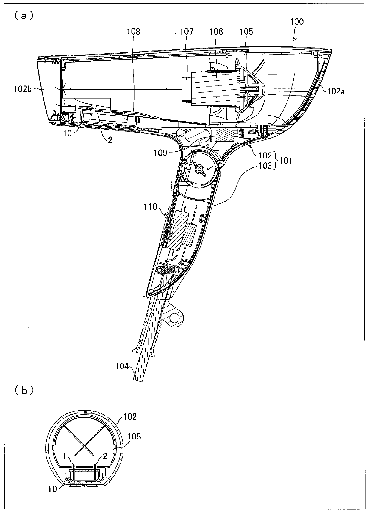
[0047] according to Figure 2 ~ Figure 6 One embodiment of the present invention will be described as follows.
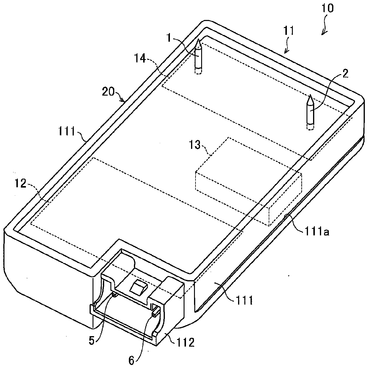
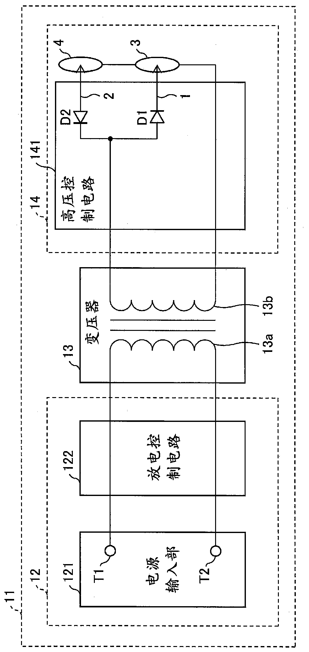
[0048] figure 2 It is a perspective view which shows the structure of the appearance of the ion generator 10 of Embodiment 1. image 3 It is a circuit diagram which shows the structure of the electric system of the ion generator 10.
[0049] Such as figure 2 As shown, the ion generator 10 is equipped with the housing 11 formed from the resin material. The housing 11 has a rectangular box-shaped body portion 20 and a connector 112 as a whole. On the two side surfaces 111 facing each other on the long side of the main body portion 20 , a step 111 a is provided along the long side direction of the side surfaces 111 . In addition, a connector 112 is provided on one of the short sides of the casing 11 . The connector 112 is connected to a connector (not shown) connected to a power supply cable. Inside the connector 112 are arranged pins 5 , 6 .
[0050] Inside ...
Embodiment approach 2
[0081] according to Figure 7 ~ Figure 10 Another embodiment of the present invention will be described as follows. In addition, for the sake of convenience of description, the same reference numerals are attached to the members having the same functions as those described in the first embodiment, and the description thereof will be omitted.
[0082] Figure 7 (a) is a plan view showing the casing 11A of the ion generating device 10 according to Embodiment 2, Figure 7 (b) is a top view which shows the other case 11B of the ion generating apparatus 10. FIG. Figure 8 (a) is a side view showing the casing 11C of the ion generating device 10 according to Embodiment 2, Figure 8 (b) is a side view which shows another casing 11D of the ion generating device 10 . Figure 9 (a) is a plan view showing the casing 11E of the ion generating device 10 according to Embodiment 2, Figure 9 (b) is a top view which shows the other case 11F of the ion generating apparatus 10. FIG. Figu...
Embodiment approach 3
[0104] according to figure 2 , Figure 11 ~ Figure 13 Another embodiment of the present invention will be described as follows. In addition, for the sake of convenience of description, the same reference numerals are attached to the members having the same functions as those described in Embodiments 1 and 2, and description thereof will be omitted.
[0105] Figure 11 It is a front view showing the structure of the ion generator 10 according to Embodiment 3, showing and installing figure 2 The side opposite the side of connector 112 is shown. Figure 12 Yes means take out from the tray Figure 11 The perspective view of the state of the ion generating apparatus 10 shown. Figure 13 It means the air duct 301 configuration in the electrical equipment Figure 11 A diagram showing the state of the ion generating device 10 is shown.
[0106] Such as figure 2 and Figure 11 As shown, the step 111 a is formed along the longitudinal direction of the side surface 111 on the...
PUM
 Abstract
Description
Claims
Application Information
 - R&D
- Intellectual Property
- Life Sciences
- Materials
- Tech Scout
- Unparalleled Data Quality
- Higher Quality Content
- 60% Fewer Hallucinations
Browse by: Latest US Patents, China's latest patents, Technical Efficacy Thesaurus, Application Domain, Technology Topic, Popular Technical Reports.
© 2025 PatSnap. All rights reserved.Legal|Privacy policy|Modern Slavery Act Transparency Statement|Sitemap|About US| Contact US: help@patsnap.com


