Hub motor for electric vehicle
A hub motor and electric vehicle technology, applied in the field of electric vehicles, can solve the problems of large waste of motor stators, low reusability of inner ring blanking, high manufacturing costs, etc., to save material costs, good motor structure stability, and use long life effect
- Summary
- Abstract
- Description
- Claims
- Application Information
AI Technical Summary
Problems solved by technology
Method used
Image
Examples
Embodiment 1
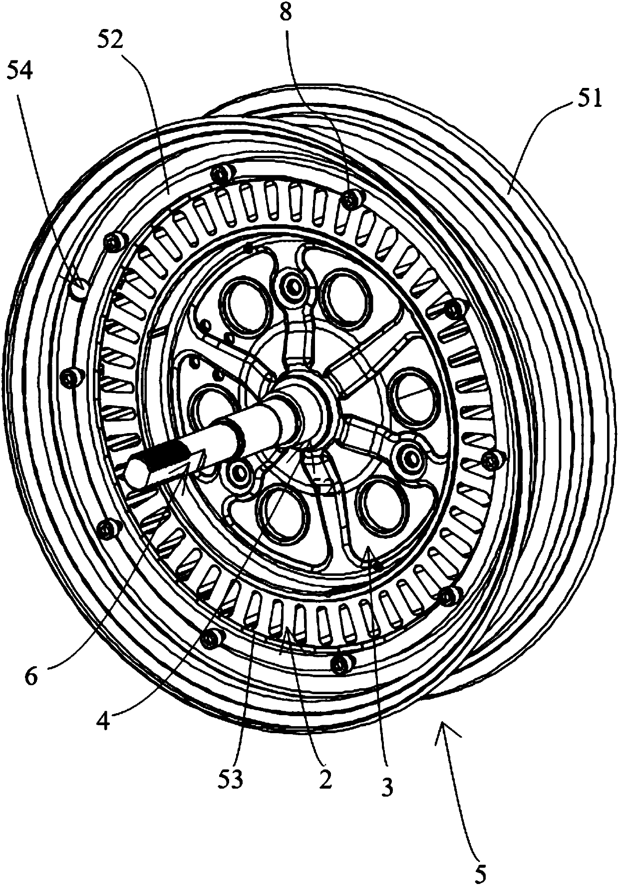
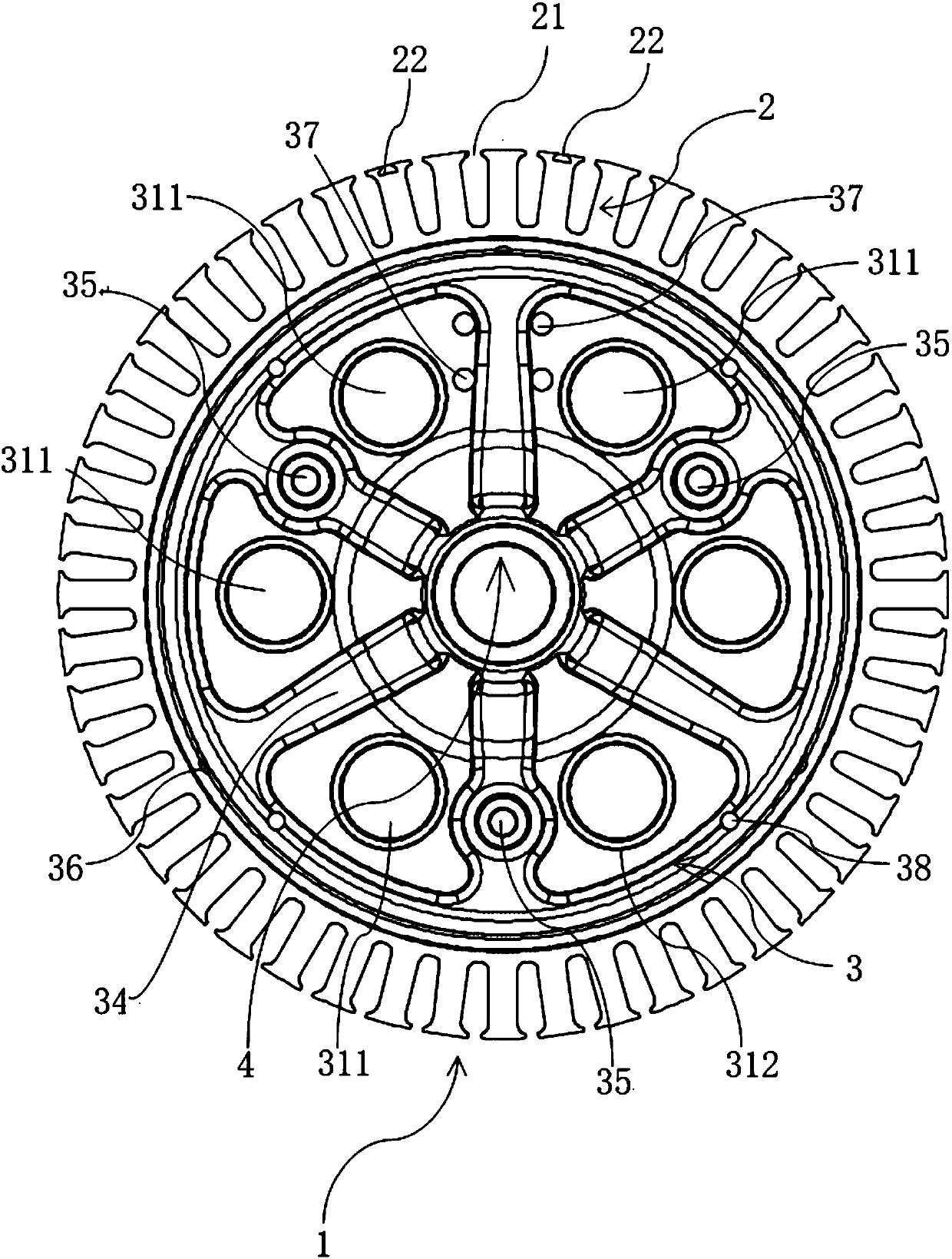
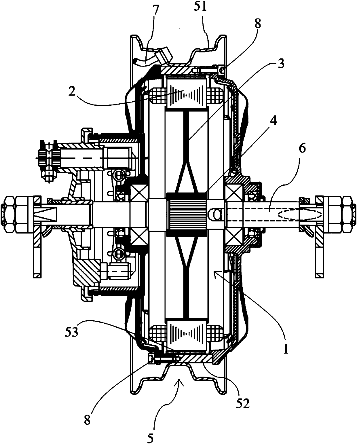
[0039] Such as Figure 1 to Figure 9 As shown, a hub motor for an electric vehicle provided in this embodiment includes a stator 1, a rotor 5, a connecting shaft 6, and other accessories such as a Hall assembly. The stator 1 and the connecting shaft 6 are circumferentially positioned, and the rotor 5 is sleeved on the stator. 1 outside, the stator 1 includes an iron core 2 and a bracket 3, the bracket 3 is fastened by two supporting plates, the edge of the supporting plate extends out of the circumferential surface 40 toward the opposite side of the opposing surface 41, and the iron core 2 is formed by tooth ribs 24. The yoke 25 and the tooth groove 23 are formed. The iron core 2 is fixed on the outer peripheral surface 40 of the support 3. The center of the support 3 is welded with a shaft sleeve 4. The axial end of the iron core 2 is provided with a number of Hall slots for installation. Hall element, iron core 2 inner circumference surface is provided with some circular arc...
Embodiment 2
[0059] The technical solutions in this embodiment are mostly the same as those in Embodiment 1. This embodiment only describes the different parts in detail, and the parts that are the same as those in Embodiment 1 will not be repeated here.
[0060]In particular, the iron core is formed by stacking layers of stator sheets in a spiral winding manner, and the tooth slots are formed by the natural rolling of the stator sheets. The thickness of the lip, the inner diameter of the iron core, the thickness of the yoke of the iron core, the number of slots of the iron core, and the slot width of the stator slice satisfy the following relationship:
[0061] Slot width of the slot = π x [outer diameter of the iron core - 2 x thickness of the tooth lip of the iron core - 2 x α x (inner diameter of the iron core + thickness of the yoke of the iron core)] ÷ number of slots of the iron core + Slot width of stator segments
[0062] Wherein π is the circumference ratio, the value range of α...
Embodiment 3
[0070] The technical solutions in this embodiment are mostly the same as those in Embodiment 1. This embodiment only describes the different parts in detail, and the parts that are the same as those in Embodiment 1 will not be repeated here.
[0071] In particular, the iron core is formed by stacking layers of stator sheets in a spiral winding manner, and the tooth slots are formed by the natural rolling of the stator sheets. The thickness of the lip, the inner diameter of the iron core, the thickness of the yoke of the iron core, the number of slots of the iron core, and the slot width of the stator slice satisfy the following relationship:
[0072] Slot width of the slot = π x [outer diameter of the iron core - 2 x thickness of the tooth lip of the iron core - 2 x α x (inner diameter of the iron core + thickness of the yoke of the iron core)] ÷ number of slots of the iron core + Slot width of stator segments
[0073] Wherein π is the circumference ratio, the value range of ...
PUM
 Abstract
Description
Claims
Application Information
 - R&D Engineer
- R&D Manager
- IP Professional
- Industry Leading Data Capabilities
- Powerful AI technology
- Patent DNA Extraction
Browse by: Latest US Patents, China's latest patents, Technical Efficacy Thesaurus, Application Domain, Technology Topic, Popular Technical Reports.
© 2024 PatSnap. All rights reserved.Legal|Privacy policy|Modern Slavery Act Transparency Statement|Sitemap|About US| Contact US: help@patsnap.com


