Refrigerator condensation heat dissipation system and control method thereof

A heat dissipation system and control method technology, applied in the field of refrigerators, can solve the problems of poor heat dissipation of micro-channel condensers and compressor shells, poor refrigeration performance, and high noise of the whole machine, so as to improve condensation heat dissipation, refrigeration demand, and heat dissipation Improved performance and efficient heat dissipation

Inactive Publication Date: 2019-07-09
CHANGHONG MEILING CO LTD
View PDF3 Cites 0 Cited by
  • Summary
  • Abstract
  • Description
  • Claims
  • Application Information

AI Technical Summary

Problems solved by technology

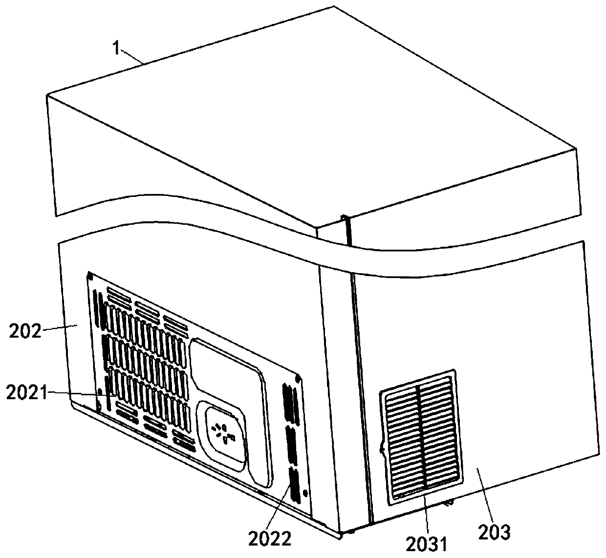
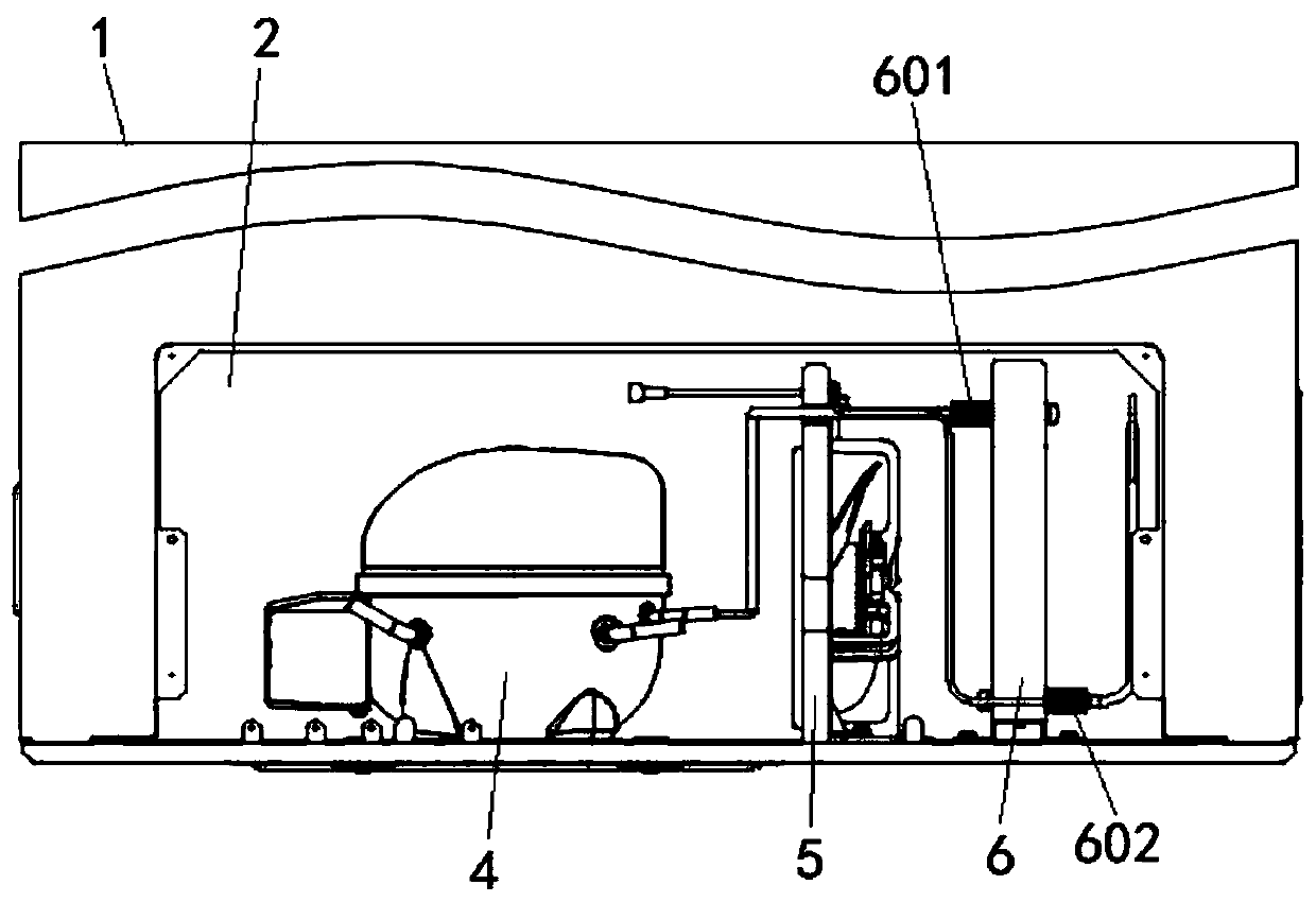
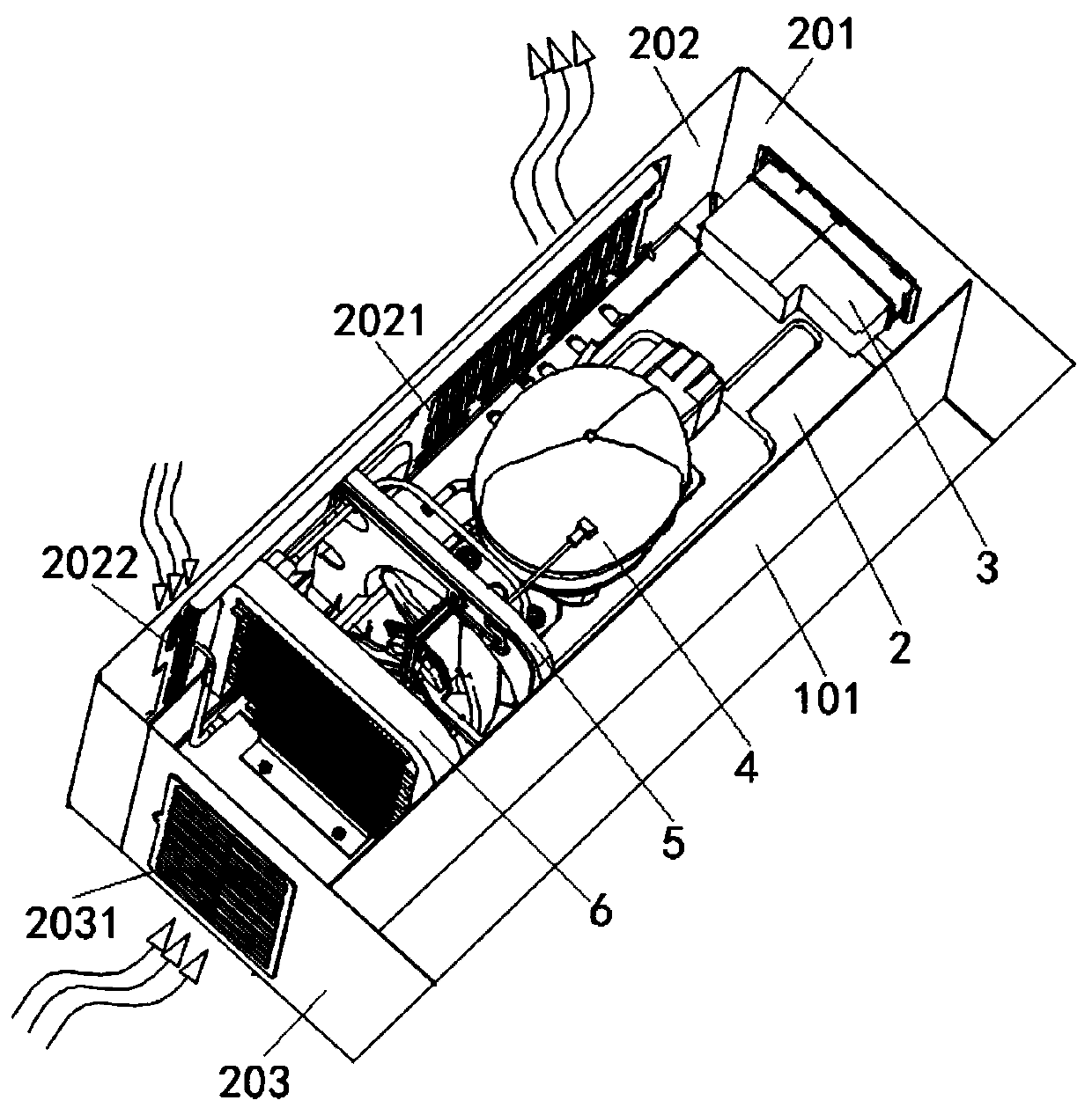
[0006] The object of the present invention is to provide a freezer condensation heat dissipation system and its control method, by setting up an air outlet and an air inlet on the ventilation hood of the machine room, and installing a louvered air outlet on the second side plate, so that the air entering from the air inlet and the louvered air outlet The air volume in the cooling room of the freezer forms a condensation air duct with efficient heat dissipation, and finally flows from the air outlet to the outside, so as to realize the efficient heat dissipation of the micro-channel condenser and the compressor, and solve the poor cooling performance of the existing freezer compressor , Micro-channel condenser and compressor shell heat dissipation is not good and the whole machine is noisy and has a short service life

Method used


Image

  • Refrigerator condensation heat dissipation system and control method thereof
  • Refrigerator condensation heat dissipation system and control method thereof
  • Refrigerator condensation heat dissipation system and control method thereof

Examples


Embodiment Construction

[0038] The following will clearly and completely describe the technical solutions in the embodiments of the present invention with reference to the accompanying drawings in the embodiments of the present invention. Obviously, the described embodiments are only some, not all, embodiments of the present invention. Based on the embodiments of the present invention, all other embodiments obtained by persons of ordinary skill in the art without creative efforts fall within the protection scope of the present invention.

[0039] In describing the present invention, it is to be understood that the terms "disposed", "open", "bottom", "top", "middle", "length", "inner", "peripheral side", etc. designate an orientation or position The relationship is only for the convenience of describing the present invention and simplifying the description, but does not indicate or imply that the components or elements referred to must have a specific orientation, be constructed and operated in a speci...


PUM


Abstract

The invention discloses a refrigerator condensation heat dissipation system and a control method of the refrigerator condensation heat dissipation system, and relates to the technical field of refrigerators. The refrigerator condensation heat dissipation system comprises a refrigerator body, the bottom of the refrigerator body is divided into a refrigerator refrigeration heat dissipation compartment through a foaming plate, and a display control component, a compressor, a variable-frequency direct-current motor fan and a microchannel condenser are sequentially arranged in the refrigerator refrigeration heat dissipation compartment, an environment temperature sensor is mounted on the display control assembly, and the inlet end and the outlet end of the microchannel condenser are provided with an inlet end temperature sensor and an outlet end temperature sensor correspondingly. An air outlet and an air inlet are formed in a cabin ventilation cover, and a louver air inlet is arranged on asecond side plate, so that the air quantity entering the refrigerator refrigeration heat dissipation compartment from the air inlet and the louver air inlet forms an efficient heat dissipation condensation air channel, and finally flows to the outside from the air outlet, so that efficient heat dissipation of the micro-channel condenser and the compressor is realized, and the air inlet quantity and the air flowing smoothness of the refrigerator refrigeration heat dissipation compartment are improved.

Description

technical field [0001] The invention belongs to the technical field of refrigerators, in particular to a condensation and heat dissipation system of a refrigerator and a control method thereof. Background technique [0002] Because of its excellent thermal performance, large cooling capacity per unit volume and low price, R290 refrigerant is a better environmental protection substitute suitable for use in large household freezers and commercial freezers. At present, the R290 compressor with a large cooling capacity needs to use fans for forced convection heat dissipation to meet the performance of the R290 compressor; [0003] In the field of R290 compressors, the maximum temperature that the winding coil of the compressor motor can withstand and the temperature of the compressor shell have a certain temperature range requirement, and the quality of the condensation cooling system directly affects the overall cooling performance and noise of the freezer; when the compression...

Claims


Application Information

Patent Timeline
Patent Type & Authority Applications(China)
IPC IPC(8): F25D11/00F25D23/00F25D29/00
CPCF25D11/00F25D23/003F25D29/003F25D29/005F25D2600/06Y02B40/00
Inventor 涂岩亮
Owner CHANGHONG MEILING CO LTD
Why Eureka
Try Eureka