A driving structure and a device with flexible joints
A technology of flexible joints and driving structures, applied in the field of medical devices, can solve problems such as large operation space, and achieve the effects of simple operation, simple structure and stable hinge structure
- Summary
- Abstract
- Description
- Claims
- Application Information
AI Technical Summary
Problems solved by technology
Method used
Image
Examples
Embodiment 1
[0048] The driving structure 9 of this embodiment, such as figure 1 , image 3 , Figure 4 As shown, it is suitable for use in a device with flexible joints, and the device with flexible joints includes a flexible joint 33 and a grip portion 2 . The drive structure 9 includes a drive body 1 and a control line 10 .
[0049] The driving body 1 is arranged between the flexible joint 33 and the holding part 2 , and the two ends of the driving body 1 are respectively connected with the flexible joint 33 and the holding part 2 , and the two ends of the driving body 1 can deflect relative to each other.
[0050] One end of the control wire 10 is connected to one end of the flexible joint 33 away from the driving body 1 , and the other end is connected to the driving body 1 . The two ends of the driving body 1 deflect relative to each other, and the distance between the connection between the flexible joint 33 and the control wire 10 and the connection between the driven body 1 and...
Embodiment 2
[0062] In this embodiment, on the basis of Embodiment 1, the driving structure 9 further includes a runner 6. The runner 6 is rotatably connected to the holding portion 2, and can drive the driving body 1 to rotate around the axis of the driving body 1. The driving body 1 passes through the first The hinge shaft is hinged with the runner 6 . In order to make the rotational speed of the runner 6 consistent with the rotational speed of the actuator, the axis of the runner 6 coincides with the axis of the actuator 3 .
[0063] In this embodiment, the specific structure is that the first hinge member 51 is hinged in the runner 6 through the first hinge shaft.
Embodiment 3
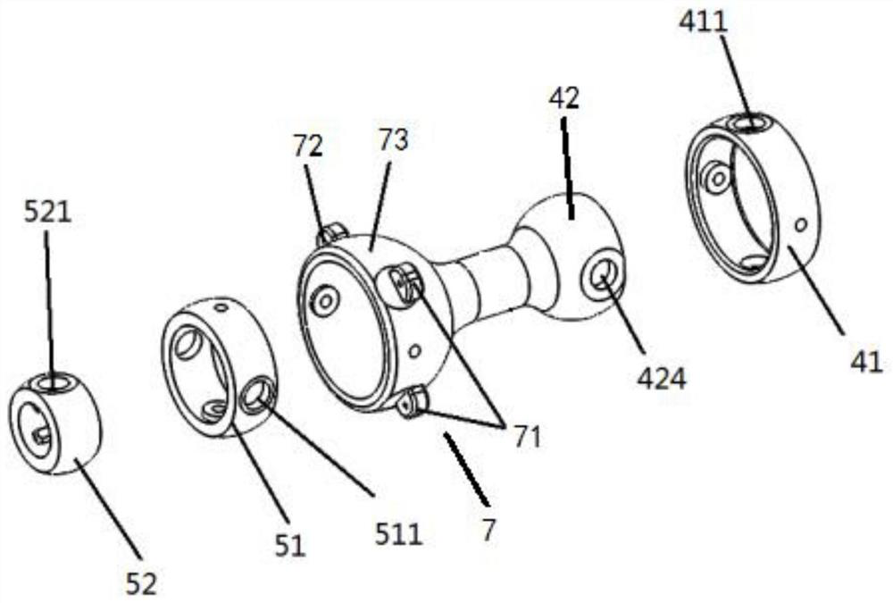
[0065] This embodiment is based on Embodiment 1, such as figure 2 , Figure 5 , Image 6 As shown, the driving body 1 further includes a second Hook hinge structure 4 disposed between the first Hook hinge structure 5 and the gripping portion 2 . The second Hooke hinge structure 4 includes a third hinge member 41 and a fourth hinge member 42 . The third hinge 41 is provided with a third hinge hole 411, a third bearing whose axis is coincident with the axis of the third hinge hole 411 is provided in the third hinge hole 411, and the third hinge shaft is disposed on the third hinge through the third bearing 41 , the third hinge member 41 is hinged in the holding portion 2 through a third hinge shaft. One end of the fourth hinge member 42 is provided with a fourth hinge hole 424, a fourth bearing whose axis is coincident with the axis of the fourth hinge hole 424 is provided in the fourth hinge hole 424, and the fourth hinge shaft is arranged on the fourth hinge through the fo...
PUM
 Abstract
Description
Claims
Application Information
 - R&D Engineer
- R&D Manager
- IP Professional
- Industry Leading Data Capabilities
- Powerful AI technology
- Patent DNA Extraction
Browse by: Latest US Patents, China's latest patents, Technical Efficacy Thesaurus, Application Domain, Technology Topic, Popular Technical Reports.
© 2024 PatSnap. All rights reserved.Legal|Privacy policy|Modern Slavery Act Transparency Statement|Sitemap|About US| Contact US: help@patsnap.com


