
Projection lens and projection system

A technology of projection lens and optical system, applied in the field of projection lens and projection system, can solve the problems of low display brightness, low luminous flux density of projection lens, and inability to realize 4K resolution projection display, etc.

Active Publication Date: 2021-03-19
HISENSE VISUAL TECH CO LTD
View PDF2 Cites 0 Cited by
  • Summary
  • Abstract
  • Description
  • Claims
  • Application Information

AI Technical Summary

Problems solved by technology

The current DLP splicing screen usually uses light emitting diode (Light Emitting Diode, referred to as LED) as the light source, but its display brightness is not high, about 1000-1500lm, and most of the DMD use the specification of 0.9", so the luminous flux density of the projection lens is relatively high. Low
With the large-scale introduction of the laser light source to the market, the laser light source is applied to the DLP splicing screen, and the 0.65” DMD can be used to increase the light energy, so the original projection lens is no longer applicable.
In addition, the existing projection lens adopts the direct projection of the cabinet, resulting in the excessive volume of the cabinet
In addition, the rear working distance of the projection lens used at this stage is generally about 35mm, and the rear working distance of this size cannot be equipped with an image shifting mirror group, so 4K resolution projection display cannot be realized

Method used


Image

  • Projection lens and projection system
  • Projection lens and projection system
  • Projection lens and projection system

Examples


Embodiment Construction

[0053] Embodiments of the present invention provide a projection lens and a projection system, which are used to adapt to a laser light source and reduce the volume of a projection box.

[0054] In order to make the above objects, features and advantages of the present invention more comprehensible, the present invention will be further described below in conjunction with the accompanying drawings and embodiments. Example embodiments may, however, be embodied in many forms and should not be construed as limited to the embodiments set forth herein; rather, these embodiments are provided so that this disclosure will be thorough and complete, and will fully convey the concept of example embodiments to those skilled in the art.

[0055] It should be noted that in the following description, specific details are set forth in order to fully understand the present invention. However, the present invention can be implemented in many other ways than those described here, and those skil...


PUM


Abstract

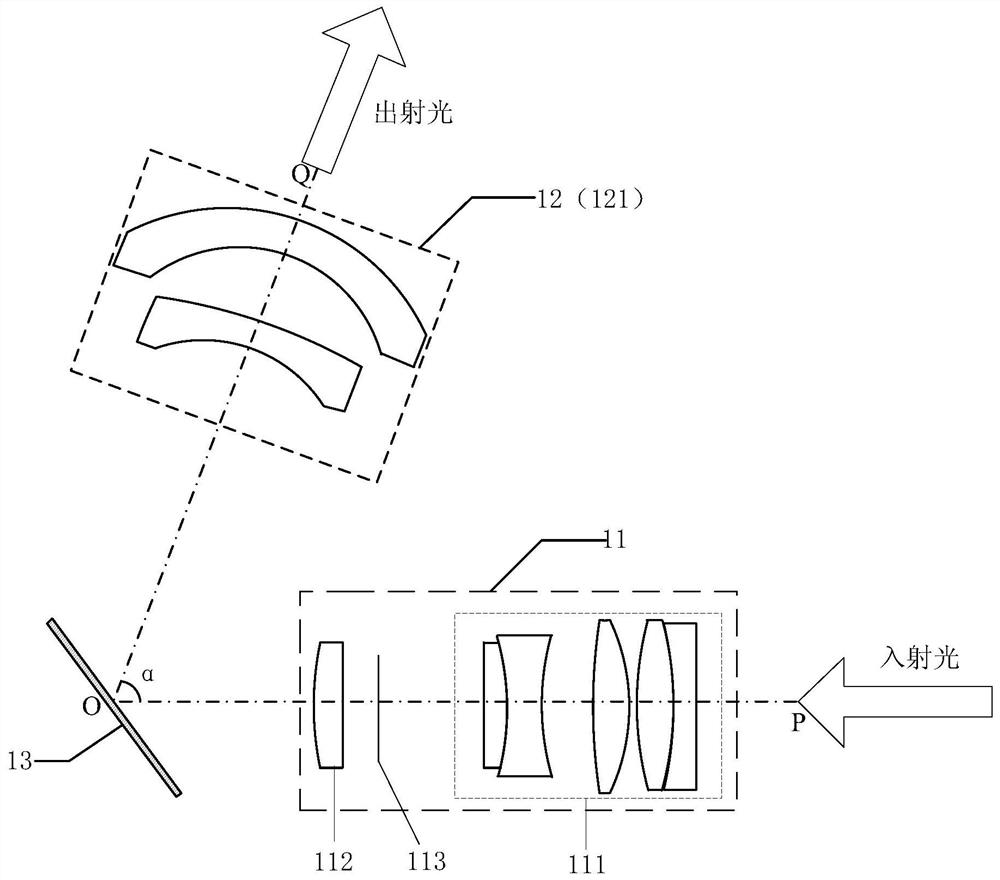
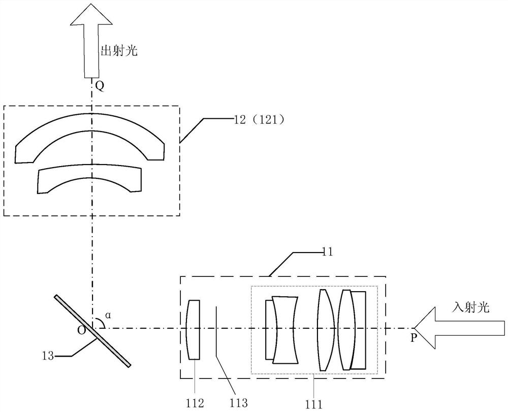
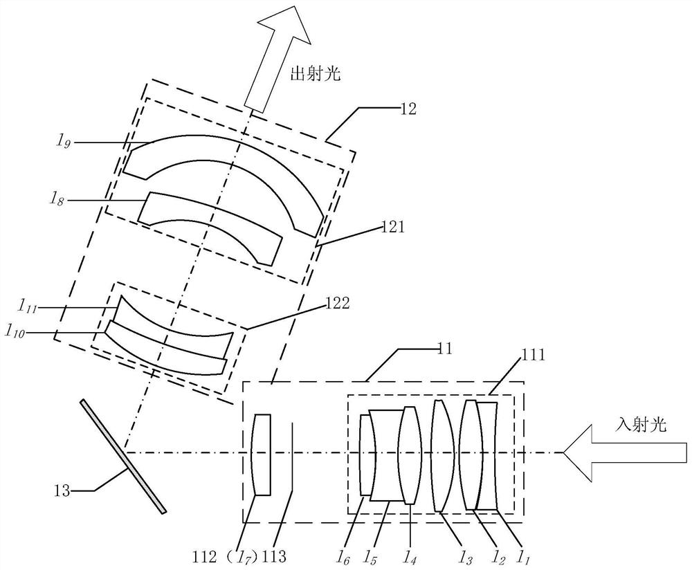
The invention relates to a projection lens and a projection system. The projection lens comprises a first optical system, a second optical system and a light path steering assembly located between thefirst optical system and the second optical system; the first optical system is used for imaging an incident light beam to form a first image; the light path steering assembly is used for reflectingthe first image of the first optical system into the second optical system; the second optical system is used for performing second imaging on the first image to form a second image; the primary optical axis of the first optical system and the primary optical axis of the second optical system form a set included angle; and the rear working distance of the projection lens ranges from 41 to 44 mm. The optical path steering assembly is adopted to enable the optical axis of the projection lens to be bent by means of a reflection light path mode, and therefore, the length of the projection lens isreduced, and the size of a projection box body is reduced; the rear working distance of the projection lens is set in the range of 41 mm to 44 mm, and a corresponding image offset lens set can be configured to realize 4k-resolution projection display.

Description

technical field [0001] The invention relates to the field of display technology, in particular to a projection lens and a projection system. Background technique [0002] Digital Light Processing (DLP for short) technology refers to the application of a digital micromirror chip (DMD) as a key processing element to realize a digital optical processing process. The principle is to divide the light emitted by the light source into primary color light, and then project it on the DMD chip, and the light processed by the DMD chip will be imaged on the projection screen through the projection lens. From the technical principle of DLP, it has the least signal noise, accurate gray scale, high reflectivity, seamless image display, high reliability and other advantages. [0003] The DLP splicing screen is spliced ​​by multiple rear projection display units. Its main feature is that the splicing seam is small and can be controlled to within 0.5 mm. Based on its advantages, in recent y...

Claims


Application Information

Patent Timeline
Patent Type & Authority Patents(China)
IPC IPC(8): G02B13/00G02B13/18
CPCG02B13/00G02B13/18
Inventor 朱瑞田勇伍雁雄
Owner HISENSE VISUAL TECH CO LTD
Learn More