
A Spatial Resolution Calibration Device for Electromagnetic Field Probe Based on Rectangular Waveguide Litter Mode

A spatial resolution, rectangular waveguide technology, applied in the direction of measuring devices, measuring electrical variables, instruments, etc., can solve the problems of unfavorable testing, small electromagnetic field gradient, etc., and achieve the effect of wide calibration bandwidth, constant field gradient, and high calibration accuracy

Active Publication Date: 2020-03-10
BEIHANG UNIV
View PDF3 Cites 0 Cited by
  • Summary
  • Abstract
  • Description
  • Claims
  • Application Information

AI Technical Summary

Problems solved by technology

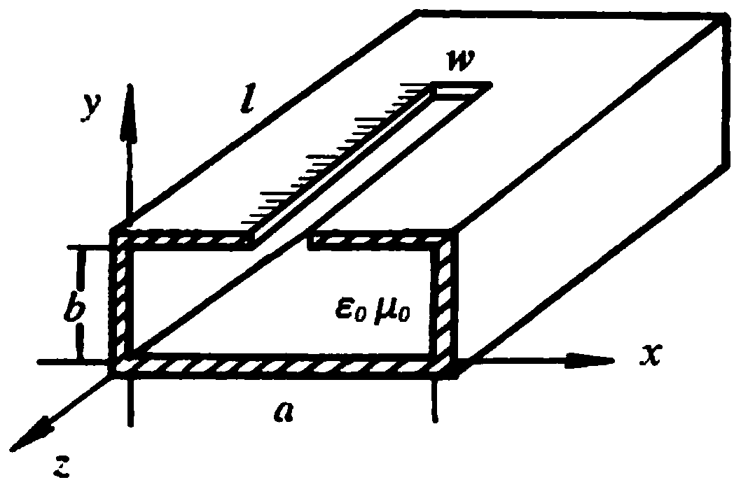
[0005] The present invention aims at the defects of the existing electromagnetic field probe spatial resolution calibration device based on TEM or quasi-TEM type transmission line that the electromagnetic field gradient is small, which is not conducive to testing, and proposes an electromagnetic field probe spatial resolution calibration device based on the rectangular waveguide litter mode, The device utilizes the fading mode of the dominant mode of the rectangular waveguide, where the dominant mode of the rectangular waveguide is TE 10 Mode, that is, the electric field exists only in the section perpendicular to the direction of propagation, and perpendicular to the broadside of the section; the magnetic field has two components

Method used


Image

  • A Spatial Resolution Calibration Device for Electromagnetic Field Probe Based on Rectangular Waveguide Litter Mode
  • A Spatial Resolution Calibration Device for Electromagnetic Field Probe Based on Rectangular Waveguide Litter Mode
  • A Spatial Resolution Calibration Device for Electromagnetic Field Probe Based on Rectangular Waveguide Litter Mode

Examples


Embodiment Construction

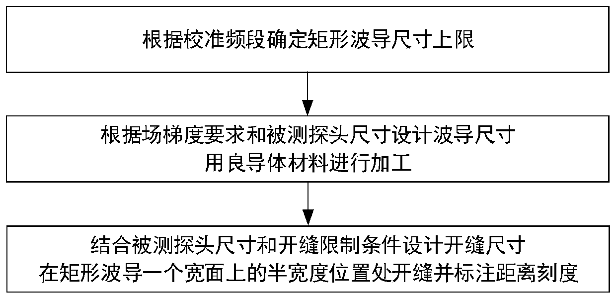
[0031] The present invention will be further described in detail below with reference to the drawings and embodiments. figure 1 Shows the design flow chart of the rectangular waveguide of the electromagnetic field probe spatial resolution calibration device based on the rectangular waveguide wither mode of the present invention, including the following steps:

[0032] The first step is to determine the upper limit of the rectangular waveguide size according to the calibration frequency band.

[0033] In order to obtain a larger field gradient, it is necessary to use the waveguide decay mode. The present invention determines the upper limit of the design of the rectangular waveguide size through the cutoff frequency condition of the waveguide. Specifically, the rectangular waveguide TE 10 The cutoff frequency of the mode (main mode) satisfies f c10 =c / 2a, where c is the speed of light in vacuum, and a is the waveguide width. When the frequency of the electromagnetic wave is lower t...


PUM


Abstract

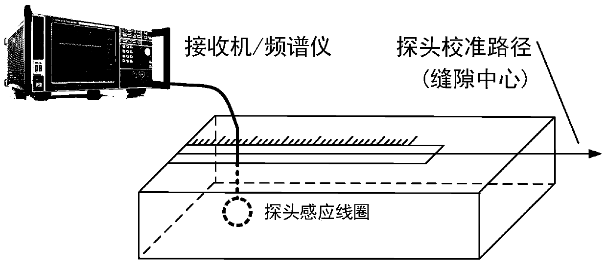
The invention discloses a rectangular waveguide evanescent mode based electromagnetic field probe spatial resolution calibration device. The device includes a rectangular waveguide connected to a matching load; the rectangular waveguide has a width a, a height b and a length l, wherein a <= 0.4c / f<max>, b < a, l > 8[lambda]c10, the c is the light velocity in vacuums, f<max> is the highest calibration frequency, and [lambda]c10 is the cut-off wavelength of a dominant mode TE10 mode of the rectangular waveguide; the half position on the upper broad wall of the rectangular waveguide is provided with a slit so as to form a calibration area; a probe can be completely stretched into the slit and move in the slit through the configuration of the width w of the slit and the height b of the rectangular waveguide; and the disturbance of the slit on a waveguide internal field structure can be in the allowed range of calibration precision through the configuration of the width w of the slit. The device is flexible and plastic in design and wide in calibration band, and can obtain large electromagnetic field gradients, so that the device is convenient in calibration operation and high in calibration precision.

Description

Technical field [0001] The invention belongs to the field of electromagnetic measurement, and in particular relates to an electromagnetic field probe spatial resolution calibration device based on a rectangular waveguide withered mode. Background technique [0002] When analyzing and correcting electromagnetic interference (EMI: Electromagnetic Interference) problems, electromagnetic field probes are often used to locate the source of radiation interference. The spatial resolution of the probe is an important parameter to evaluate its positioning accuracy. [0003] The spatial resolution of the electromagnetic field probe is considered to be the minimum spatial movement distance that can distinguish the changes in the electromagnetic field distribution. At present, there are two main calibration methods: the first is to input a signal at the source end of a microstrip line, and then translate the probe horizontally (that is, perpendicular to the transmission direction) at a certai...

Claims


Application Information

Patent Timeline
Patent Type & Authority Patents(China)
IPC IPC(8): G01R35/00
CPCG01R35/005
Inventor 戴飞胡瑞韬金赟韬
Owner BEIHANG UNIV
Learn More