Automatic oiling machine

A fuel dispenser and automatic technology, applied in the directions of engine components, engine lubrication, mechanical equipment, etc., can solve the problems of poor working environment, uncontrollable speed of grease injection, difficult implementation, etc. Solve the effect of low coating efficiency and good lubrication effect

Pending Publication Date: 2019-07-05
SHANDONG GURUN ENG TECH
View PDF0 Cites 1 Cited by
  • Summary
  • Abstract
  • Description
  • Claims
  • Application Information

AI Technical Summary

Problems solved by technology

At present, the most commonly used grease filling device is mainly a lever-type grease gun, commonly known as a grease gun, which is generally driven by manpower. It is mainly composed of a spring-loaded cylinder and a grease injection handle. Squeeze out the butter, hold the handle once and squeeze the butter once, the grease output is not continuous and uniform, it is suitable for occasions where the lubrication points are scattered and the amount of grease injection is small
If the amount of grease required is large, the number of times to turn the handle is too large. This method of greasing is time-consuming and laborious, and the grease is not uniform and continuous.
There are also patents disclosing a pneumatic or electric greasing device, which can reduce the labor intensity of workers, improve labor efficiency, and can also realize automatic continuous grease injection, but the grease injection speed cannot be adjusted, and the grease injection speed cannot be monitored and adjusted in real time
[0003] For large-scale equipment, especially high-height equipment, such as large-scale cranes widely used in fields such as petroleum mines, port logistics, civil engineering, and industrial production, the above-mentioned manually operated grease guns, pneumatic or electric greasing devices are not suitable. Very applicable, because the lubrication points on the machine are scattered, workers need to climb to each part of the machine to refill each lubrication point every time they refill, which is troublesome to operate, labor-intensive, poor working environment, and poor safety; Moreover, adding butter to a machine that cannot be stopped during operation is highly dangerous and likely to cause manual work accidents
Moreover, the weather of the operation, including wind, waves and other external environmental factors, are greatly affected, and it is not easy to carry out specific work; because it is a high-altitude operation, sometimes the situation of operators falling and causing casualties; The workload is heavy, and it is difficult to implement during the operation process. The blind area may not be applied, and the effect is not ideal. The uneven thickness of the grease application results in a large waste of manpower and material resources.

Method used


Image

  • Automatic oiling machine
  • Automatic oiling machine
  • Automatic oiling machine

Examples


Embodiment Construction

[0031] In order to clearly illustrate the technical features of this solution, the present invention will be further described below through non-limiting examples and in conjunction with the accompanying drawings.

[0032] The front, back, left, and right directions in the present invention are described based on the front, back, left, and right directions shown in the accompanying drawings. For ease of description, only parts related to the embodiments of the present invention are shown.

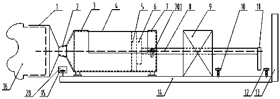
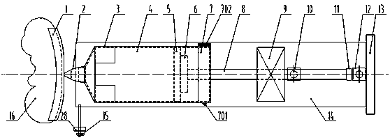
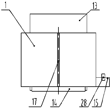
[0033]An automatic fuel dispenser, comprising a controller, a frame 14, an oil applicator 1 and an oil storage tank 4, the oil storage tank 4 has a structure similar to a glass glue tank, and is a package of lubricating oil, which has a rigid The tank body has a movable piston-type tank bottom 5 at the rear end, and a conical oil outlet nozzle 26 at the front end to push the tank bottom 5, and the lubricating oil 27 can be squeezed out from the conical oil outlet nozzle 26, and the lubricat...


PUM


Abstract

The invention discloses an automatic oiling machine. The machine comprises a controller, a rack, an oil applying device and an oil storage tank; the rear end of the oil storage tank is provided with amovable piston type tank bottom, the tank bottom is pushed, lubricating oil can be extruded from a conical oil outlet nozzle in the front end, a lubricating oil pushing mechanism and an oil storage tank support are arranged on the rack, an adapting pipe is arranged on the front end of the oil storage tank support, the oil applying device is connected with the front end of the adapting pipe, the oil storage tank is placed on an oil storage tank support, the conical oil outlet nozzle of the front end of the oil storage tank is inserted into the adapting pipe, the tank bottom on the rear end ofthe oil storage tank is in abut joint with a pushing disc, the pushing disc is connected with the work end of a lubricating oil pushing mechanism, during use, an oil distribution cavity in the oil applying device is aligned with the part, required to be charged with the lubricating oil, of a mechanical device, the lubricating oil pushing mechanism is started, the lubricating oil can be extruded into the oil distribution cavity, the lubricating oil can be automatically injected into the portion, required to be lubricated, of the machine, during filling, the manual lubricating repeated procedureis reduced, the automation degree is high, and the problems that the work is tedious, dirty, tired and dangerous can be solved.

Description

technical field [0001] The invention relates to a lubricating oil filling device in the field of mechanical engineering, in particular to a fueling device with an electric controllable fueling amount, and in particular to an automatic oiling machine with an open kinematic pair. Background technique [0002] Mechanical equipment must pay attention to maintenance during use, and lubrication is an important link throughout. There is friction in the relative movement of contact surfaces, which consumes energy and causes wear of parts. It is estimated that 1 / 3-1 / 2 of the world's energy is consumed by friction and heat, and about 80% of parts are damaged due to wear. Therefore, strengthening the lubrication of mechanical equipment is of great significance to improving the reliability of mechanical equipment, prolonging the service life, reducing equipment maintenance costs, and reducing mechanical equipment failures. According to statistics, about 40% of mechanical equipment fai...

Claims


Application Information

Patent Timeline
Patent Type & Authority Applications(China)
IPC IPC(8): F16N7/24F16N21/04F16N29/02
CPCF16N7/24F16N21/04F16N29/02
Inventor 张元恒李云鹏黄勇鹏孙常岭
Owner SHANDONG GURUN ENG TECH
Why Eureka
Try Eureka