
Multi-functional machine tool

A multifunctional machine tool and machine tool body technology, applied in the field of multifunctional machine tools, can solve problems such as machining errors, achieve the effects of eliminating violent shaking, low manufacturing cost, and simple structure

Inactive Publication Date: 2019-07-05
浦江升广科技有限责任公司
View PDF8 Cites 10 Cited by
  • Summary
  • Abstract
  • Description
  • Claims
  • Application Information

AI Technical Summary

Problems solved by technology

[0002] A machine tool refers to a machine that manufactures a machine, also known as a machine tool or a machine tool. It is customarily referred to as a machine tool. The machining accuracy of a machine tool is an important indicator to measure the development of a country's manufacturing industry. Therefore, how to improve the accuracy of a machine tool is the current technical personnel need to overcome It is a difficult problem. In the existing processing technology, for the processing of shaft parts, the turning operation axle shoulder is usually used, and the milling operation is milling the keyway. However, turning and milling are two different processing technologies of machine tools. After completing a processing technology, it is necessary to Dismantling the workpiece and installing it on the next machine tool for processing, because there is an operation of re-fixing the workpiece in the middle, this creates a new machining error

Method used


Image

  • Multi-functional machine tool
  • Multi-functional machine tool
  • Multi-functional machine tool

Examples


Embodiment Construction

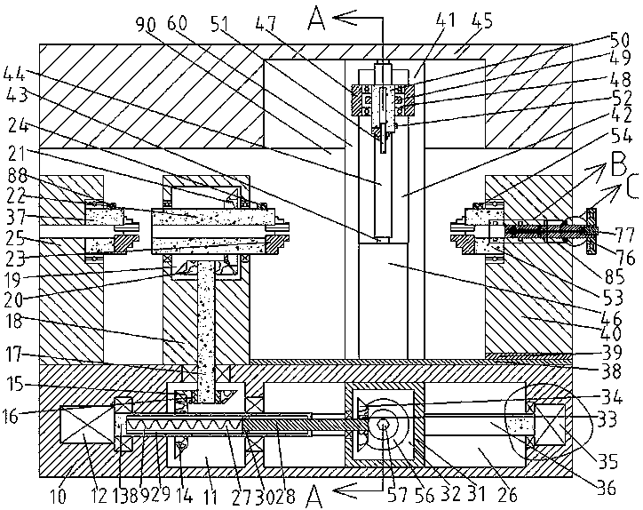
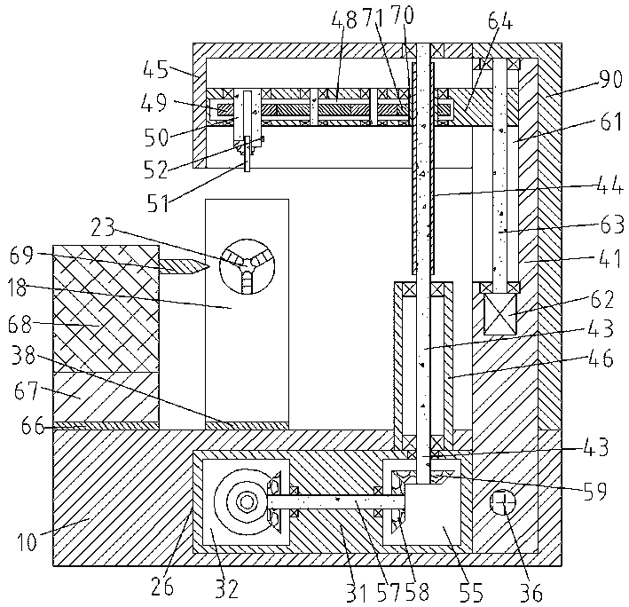
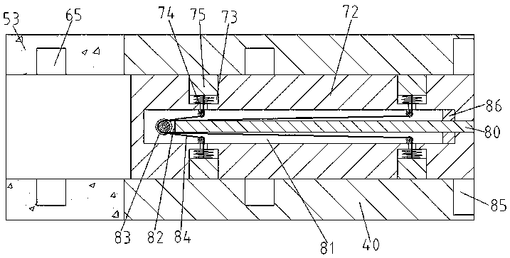
[0018] Combine below Figure 1-4 The present invention is described in detail, and for convenience of description, the orientations mentioned below are now stipulated as follows: figure 1 The up, down, left, right, front and back directions of the projection relationship itself are the same.

[0019] refer to Figure 1-4, a multifunctional machine tool according to an embodiment of the present invention includes a machine tool main body 10, an engagement cavity 11 is provided in the machine tool main body 10, and a main motor 12 is provided in the left inner wall of the engagement cavity 11. The right end of the main motor 12 is power-fitted with a transmission main shaft 13 extending into the meshing cavity 11. The transmission main shaft 13 is provided with a first bevel gear 14, and the upper side of the first bevel gear 14 is meshed with a second bevel gear. Gear 15, the first ratchet 16 is provided at the axis of the second bevel gear 15, the first ratchet 16 inner ring...


PUM


Abstract

The invention discloses a multi-functional machine tool. The multi-functional machine tool comprises a machine tool body, wherein an engaging cavity is formed in the machine tool body in a fixed mode,a main motor is fixedly arranged in the inner wall of the left side of the engaging cavity, a main transmission shaft extending into the engaging cavity is connected to the right end of the main motor in a driving cooperation mode, a first bevel gear is fixedly arranged on the main transmission shaft, and a second bevel gear is engaged with the upper side of the first bevel gear; the level of themachining accuracy of the machine tool is an important index to measure the developing degree of the national manufacturing industry, how to improve the machining accuracy of the machine tool is therefore a problem technical personnel need to solve currently. In the prior machining art, lathing a shaft shoulder by using lathing operation, milling a key slot by using milling operation are usuallyused when shaft parts are machined, but lathing and milling are two different machining processes of the machine tool, after a machining process is completed, a workpiece needs to be dismounted and then be mounted onto another machine tool to be machined, and because of the existence of an operation of re-fixing the workpiece during the process, new machining errors are generated.

Description

technical field [0001] The invention relates to the field of novel processing technology, in particular to a multifunctional machine tool. Background technique [0002] A machine tool refers to a machine that manufactures a machine, also known as a machine tool or a machine tool. It is customarily referred to as a machine tool. The machining accuracy of a machine tool is an important indicator to measure the development of a country's manufacturing industry. Therefore, how to improve the accuracy of a machine tool is the current technical personnel need to overcome It is a difficult problem. In the existing processing technology, for the processing of shaft parts, the turning operation axle shoulder is usually used, and the milling operation is milling the keyway. However, turning and milling are two different processing technologies of machine tools. After completing a processing technology, it is necessary to The workpiece is disassembled and installed on the next machine ...

Claims


Application Information

Patent Timeline
IPC IPC(8): B23P23/02B23Q5/10B23Q5/34B23B31/16
CPCB23B31/16B23P23/02B23Q5/10B23Q5/34
Inventor 刘秀飞
Owner 浦江升广科技有限责任公司
Learn More