
On-line testing device for dynamic friction performance of paired angular contact ball bearings

An angular contact ball bearing and dynamic friction technology, which is applied in mechanical bearing testing, measuring devices, testing of mechanical components, etc., can solve the problems of inability to measure the friction torque of a single bearing, inconvenient adjustment of the axial preload, and centering of the sleeve Locking difficulties and other problems can be achieved to protect the contact damage, overcome the interference caused by the motion state of the bearing, and simplify the experimental steps

Active Publication Date: 2019-07-02
SHANGHAI UNIV +1
View PDF8 Cites 8 Cited by
  • Summary
  • Abstract
  • Description
  • Claims
  • Application Information

AI Technical Summary

Problems solved by technology

[0003] The purpose of the present invention is to overcome the difficulty of centering and locking the sleeve of the matching bearing outer ring in the locking part of the original patent, and to use the free and centering locking of the sleeve to measure the real-time dynamic friction torque and vibration of the bearing respectively. It is easy to interfere with the normal operation of the bearing, it is inconvenient to adjust the axial preload of the bearing under test, and it is impossible to measure the friction torque of a single bearing. Without any adjustments to the testing machine, the dynamic friction torque, vibration and temperature of a single bearing can be measured simultaneously, and the dynamic wear of the bearing can also be measured online for a long time

Method used


Image

  • On-line testing device for dynamic friction performance of paired angular contact ball bearings
  • On-line testing device for dynamic friction performance of paired angular contact ball bearings
  • On-line testing device for dynamic friction performance of paired angular contact ball bearings

Examples


Embodiment 1

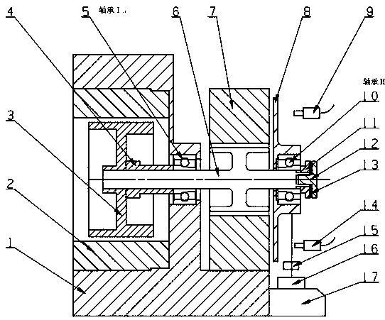
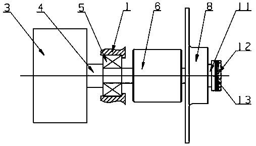
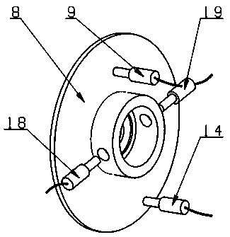
[0023] Such as figure 1 , 2 , 3, 4, and 5, an online test device for dynamic friction performance of paired angular contact ball bearings, including base 1, motor 2, 3, support shaft 6, paired bearings 5, 10, loading mechanism and measurement part. The stator 2 of the motor is fixed on the base 1, the motor rotor 3 is directly connected with the support shaft 6, the support shaft 6 is installed in the hole of the air bearing 7 in the radial direction, and the thrust surface of the air bearing 7 and the thrust disc 8 limit the support shaft The displacement of 6 to the left, the bearing I5 and the base 1 limit the displacement of the support shaft 6 to the right to realize the axial positioning of the shaft system. The low friction torque rotates, driving the paired bearings 5 ​​and 10 to rotate; the measuring part has two non-contact displacement sensors 9 and 14 installed in front of the thrust disc 8, which can measure the distance between the thrust disc 8 and the radial a...

Embodiment 2

[0024] Embodiment 2: This embodiment is basically the same as Embodiment 1, and the special features are as follows:


PUM


Abstract

The invention relates to an on-line testing device for the dynamic friction performance of paired angular contact ball bearings. On the basis of the principle of air suspension, the non-contact axialloading of a tested bearing II is obtained while the ultra-low friction support of the high-speed rotating spindle is realized by combining the measurement and adjustment technologies of precision displacement; and the friction torque of the tested bearing II is measured by using a friction torque measuring device put forward by the patent named as "high-speed miniature bearing dynamic friction torque measuring instrument" with the application number of 201610639490.9 in the research group, thereby realizing simultaneous on-line measurement of the friction torque, vibration, temperature and wearing amount of a single precision bearing. Since the outer ring of a partner tested bearing I is fixed on a base, right movement of the shafting is limited and when the shafting is in a static stateand does not work, the shafting, together with non-working faces of the radial-axial air bearing and the thrust disc, bears the shafting torque balancing after careful balance weight, thereby protecting the non-working surface of the high-precision radial-axial air bearing from being in contact for long time and being damaged.

Description

technical field [0001] The invention relates to an online test device for dynamic friction performance of paired angular contact ball bearings, which is a simultaneous online test device for simulating friction torque, vibration, temperature and wear of angular contact ball bearings under actual working conditions. Background technique [0002] Angular contact ball bearings are generally used in very precise and light-loaded occasions, such as the gyroscope of satellite inertial instruments, which determines that the failure mode is not fatigue failure, but the excessive fluctuation of the friction torque of the bearing affects the stability of the bearing or due to Excessive wear leads to reduced bearing accuracy and premature failure. These two failure modes are caused by the degradation of the lubricant and the wear between the ball and the inner and outer rings of the raceway after the bearing has been in operation for a long time, and the specific failure cannot be pred...

Claims


Application Information

Patent Timeline
Patent Type & Authority Applications(China)
IPC IPC(8): G01M13/04G01M13/045
CPCG01M13/04G01M13/045
Inventor 陈晓阳陈世金余春江沈雪瑾
Owner SHANGHAI UNIV
Learn More