
Multifunctional valve, zero-cold-water water heater and water flow control method

A technology of multi-function valve and water heater, which is applied in the fields of multi-function valve, water flow control and zero cold water water heater, can solve the problems of low control accuracy and achieve the effect of accurate outlet water temperature and stable operation.

Pending Publication Date: 2019-07-02
NINGBO FOTILE KITCHEN WARE CO LTD
View PDF1 Cites 3 Cited by
  • Summary
  • Abstract
  • Description
  • Claims
  • Application Information

AI Technical Summary

Problems solved by technology

This utility model controls the movement of the piston through a temperature-sensitive thermal expansion rod to adjust the mixing ratio of cold water and hot water, which not only has serious control hysteresis, but also has low control accuracy, and is not suitable for zero-cold water gas water heaters under pressurized conditions.

Method used


Image

  • Multifunctional valve, zero-cold-water water heater and water flow control method
  • Multifunctional valve, zero-cold-water water heater and water flow control method
  • Multifunctional valve, zero-cold-water water heater and water flow control method

Examples


Embodiment

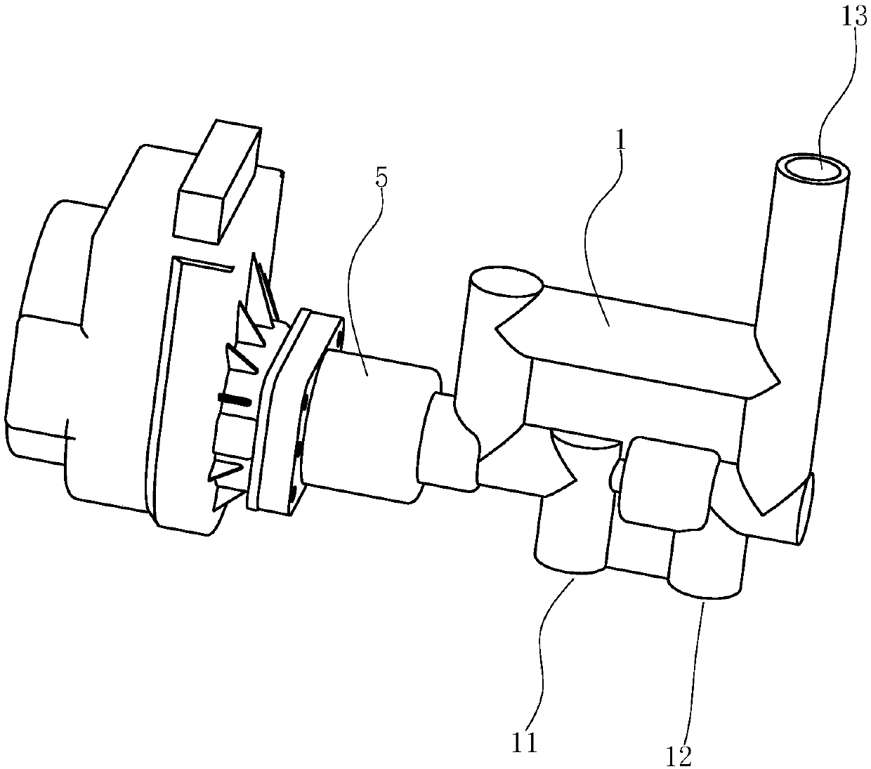
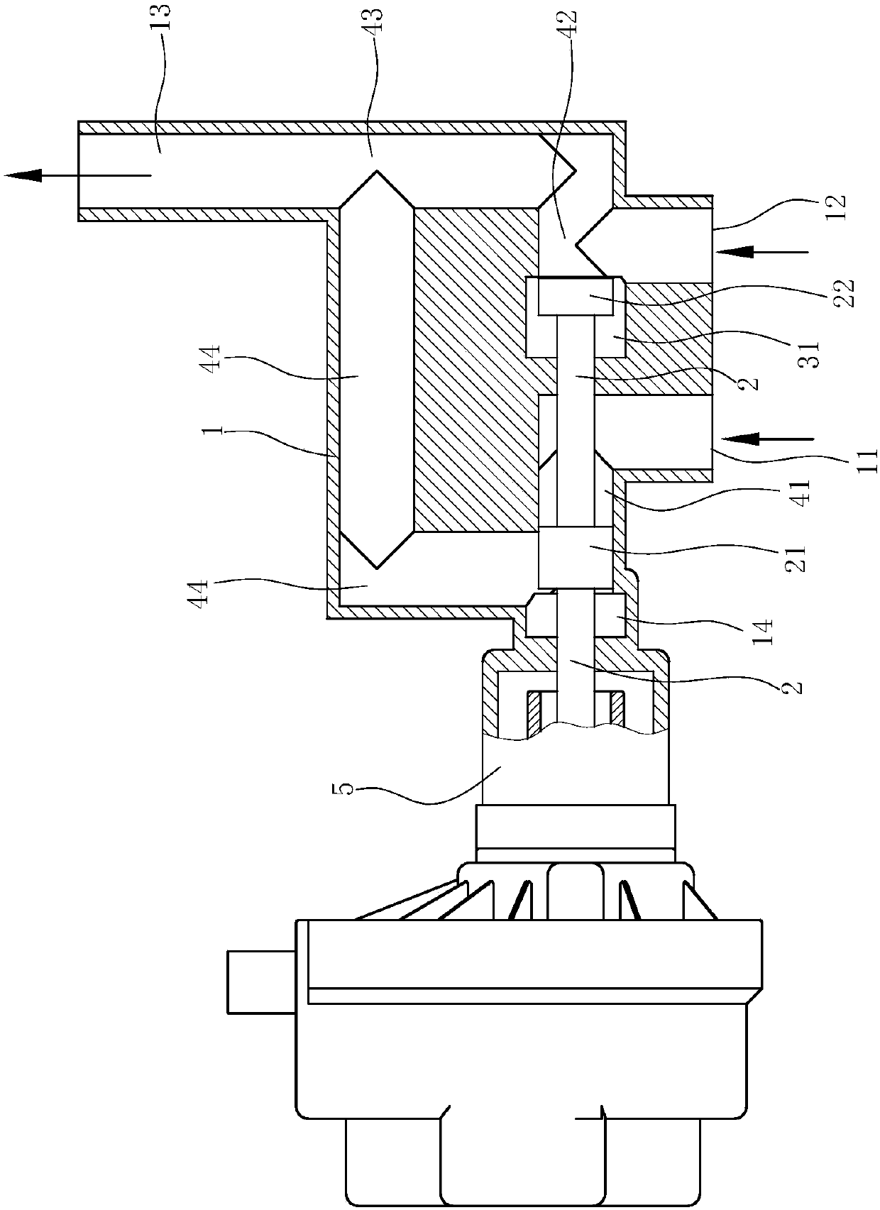
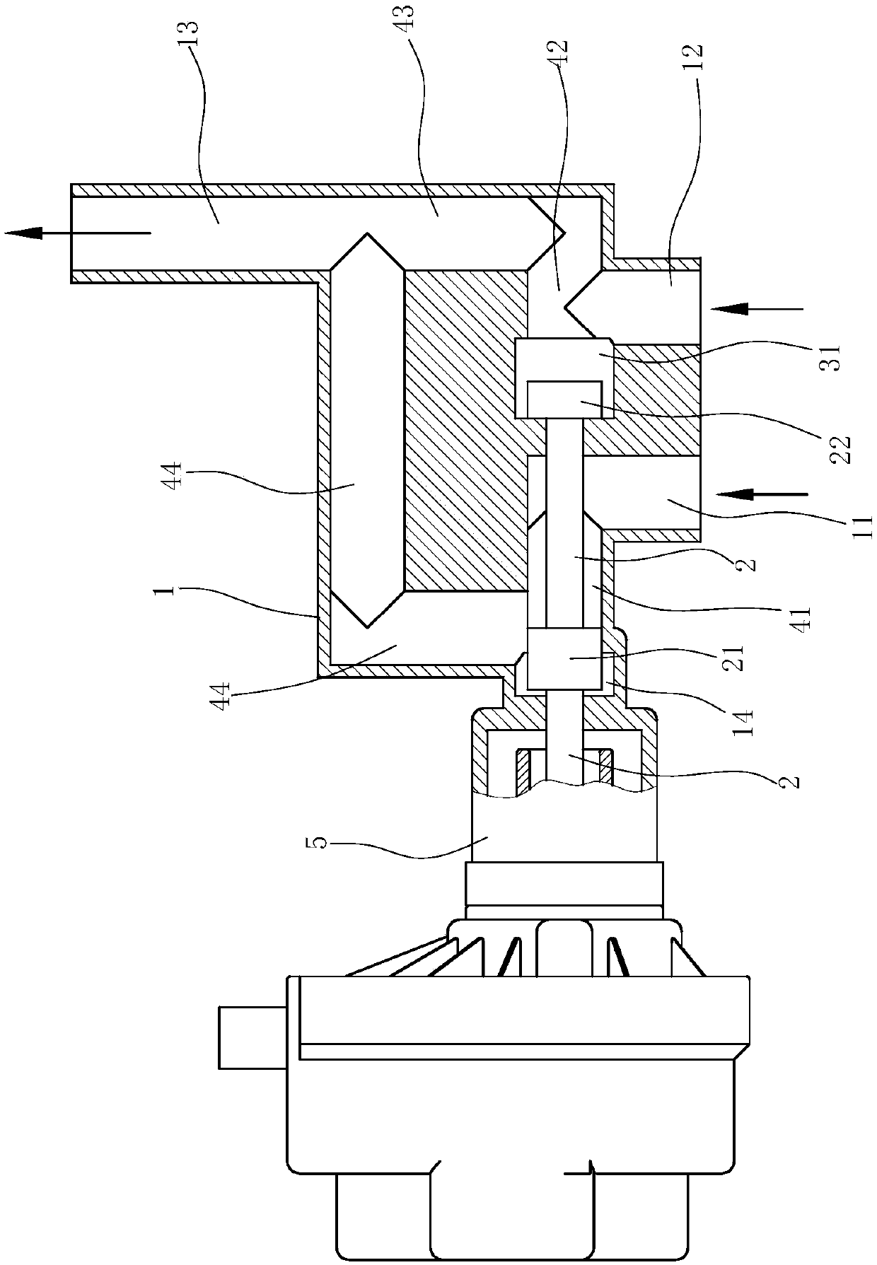
[0031] Such as Figure 1 to Figure 3 As shown, the multi-function valve includes:

[0032] The valve body 1 is provided with a first water inlet 11, a second water inlet 12 and a water outlet 13 communicating with the valve cavity of the valve body 1;

[0033] The valve seat 3 is arranged in the valve chamber of the valve body 1, and divides the valve chamber into a first water inlet chamber 41 communicated with the first water inlet 11 and a second water inlet chamber communicated with the second water inlet 12. chamber 42, a water outlet chamber 43 communicating with the water outlet 13, and a circulation chamber 44 communicating with the first water inlet chamber 41 and the water outlet chamber 43, and the second water inlet chamber 42 communicating with the water outlet chamber 43 . The valve seat 3 is also provided with a perforation for the valve stem 2 to pass through.

[0034] In this embodiment, the cross section of the valve seat 3 is "T" shape, its first part is ...

Embodiment 2

[0043] Such as Figure 4 shown in Example 1 using Figure 1 to Figure 3 Zero cold water water heater with multi-function valve shown.

[0044] The first water inlet 11 of the multi-function valve is connected to the circulating water pipeline 61 of the water heater, the second water inlet 12 is connected to the tap water pipeline 62, the water outlet 13 is connected to the water inlet pipeline 63 of the water heater, and the water inlet pipeline 63 of the water heater is provided with a circulation pump 7 , temperature sensor 64 and pressure sensor 65.

[0045] The circulation pump 7 , the motor 5 , the pressure sensor 65 and the temperature sensor 64 are all electrically connected to the control circuit 66 of the water heater.

[0046] All the other structures of the water heater are identical with the prior art.

[0047] The water flow control method of this zero cold water water heater is as follows:

[0048]When the water heater is performing the zero cold water progra...


PUM


Abstract

The invention relates to a multifunctional valve, a zero-cold-water water heater and a water flow control method. The multifunctional valve comprises a valve body, water inlets and a water outlet which communicate with a valve cavity of the valve body are formed in the valve body, and a valve rod is arranged in the valve body. The multifunctional valve is characterized in that the water inlet comprises the first water inlet and the second water inlet, a valve seat is arranged in the valve cavity, the valve seat is used for separating the valve cavity into a first water inlet cavity communicating with the first water inlet body, a second water cavity communicating with the second water inlet, a water outlet cavity communicating with the water outlet, and a circulating cavity which is used for enabling the first water inlet cavity to communicate with the water outlet cavity, the second water inlet cavity communicates with the water outlet cavity, and a first piston corresponding to the first water inlet and the circulating cavity and a second piston corresponding to the second water inlet are arranged on the valve rod at an interval.

Description

technical field [0001] The invention relates to the field of water heaters, in particular to a multifunctional valve, a zero cold water water heater using the multifunctional valve and a water flow control method of the zero cold water water heater. Background technique [0002] CN201420272733.6 discloses "A Three-way Regulating Valve", which includes a valve body, a valve core, a water inlet A, a water inlet B and a control valve. The valve core is located in the valve body, and the water inlet A and water inlet B are respectively located on the valve body , the control valve is located on the water inlet B, characterized in that the horizontal position of the water inlet A is higher than the horizontal position of the water inlet B, the valve core is located between the water inlet A and the water inlet B and is connected to one end of the thermal expansion rod, The other end of the thermal expansion rod is connected to the fixed plate, and the fixed plate is fixedly conne...

Claims


Application Information

Patent Timeline
IPC IPC(8): F16K11/044F16K31/04F16K37/00F24H9/20
CPCF16K11/044F16K31/04F16K37/0091F24H9/2007
Inventor 黄启彬朱海龙周高云
Owner NINGBO FOTILE KITCHEN WARE CO LTD
Learn More