Ultrasonic imaging method, ultrasonic elastography methods and miniature ultrasonic device
An ultrasonic imaging method and ultrasonic technology, applied in the field of ultrasound, can solve the problem that the circular cross-sectional imaging of the circular target area cannot be realized, and achieve the effect of fast shear wave elastography and fast imaging speed
- Summary
- Abstract
- Description
- Claims
- Application Information
AI Technical Summary
Problems solved by technology
Method used
Image

Examples
Embodiment 1
[0099] This embodiment provides an ultrasonic beam synthesis method, such as Figure 4 shown, including the following steps:
[0100] S11: Obtain the distance between the at least two series-connected ultrasonic transducer arrays and the target focal point and the initial wave velocity of the ultrasonic waves in the target area, each transducer in the ultrasonic transducer arrays faces the same plane. In this embodiment, in order to improve the focusing effect of the ultrasonic velocity and improve the energy utilization rate, the normal lines at the centers of the at least two series-connected ultrasonic transducer arrays are preferably located in the same plane, and the centers of each ultrasonic transducer array are in line with the target The included angle between the line connecting the focus points and the normal line is preferably smaller than a preset angle.
[0101] S12: Obtain the initial transmission parameters of each ultrasonic transducer array according to the ...
Embodiment 2
[0122] Such as Figure 7 As shown, the present embodiment provides an ultrasonic imaging method, comprising the following steps:
[0123] S21: Using multiple ultrasonic transducers in the same ring direction to transmit a plane wave composed of non-focused ultrasonic beams to the target area and receive ultrasonic echo signals, the target area includes an annular target area;
[0124] S22: Obtain a cross-sectional ultrasound image of the target area according to the ultrasound echo signal.
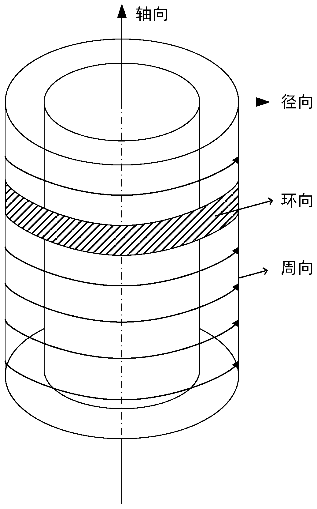
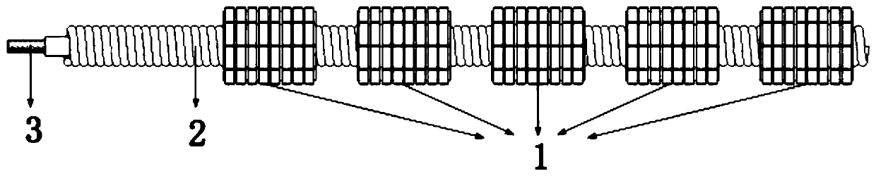
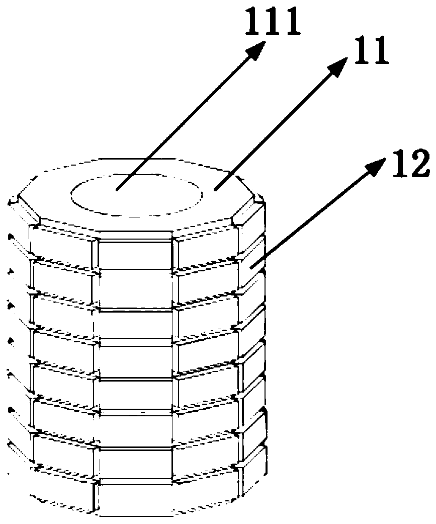
[0125] Specifically, the above-mentioned multiple ultrasonic transducers in the same circular direction form an ultrasonic circular transducer array. In this implementation, the ultrasonic hoop transducer array is arranged coaxially with the annular target area, and the ultrasonic hoop transducer array is used to emit non-focused plane waves and receive ultrasonic echo signals, so that the ultrasonic hoop transducer array The cross-sectional imaging of the target area in the axial direct...
Embodiment 3
[0139] Such as Figure 10 As shown, the present embodiment provides a method for ultrasonic elastography, comprising the following steps:
[0140] S31: Use multiple annular ultrasonic transducer arrays coaxially connected in series to transmit non-focused ultrasonic plane waves to the target area to obtain initial ultrasonic echo signals at different circumferential positions of the target area, and the annular ultrasonic transducer array is also set For multiple ultrasonic transducers on the same ring, the target area includes a circular target area, or a non-closed arc target area;
[0141] S32: Transmitting a shear wave excitation beam along at least one radial direction of the target area, such as Figure 11 shown;
[0142] S33: using a plurality of circular ultrasonic transducer arrays to transmit non-focused ultrasonic plane waves to the target area to obtain ultrasonic echo signals at different circumferential positions of the target area after the shear wave is gener...
PUM
 Abstract
Description
Claims
Application Information
 - R&D
- Intellectual Property
- Life Sciences
- Materials
- Tech Scout
- Unparalleled Data Quality
- Higher Quality Content
- 60% Fewer Hallucinations
Browse by: Latest US Patents, China's latest patents, Technical Efficacy Thesaurus, Application Domain, Technology Topic, Popular Technical Reports.
© 2025 PatSnap. All rights reserved.Legal|Privacy policy|Modern Slavery Act Transparency Statement|Sitemap|About US| Contact US: help@patsnap.com