
Ultrasonic beam synthesizing method, ultrasonic imaging method and ultrasonic elastography method

An ultrasonic and ultrasonic echo technology, applied in ultrasonic/sonic/infrasonic diagnosis, sonic diagnosis, infrasonic diagnosis, etc., can solve the problems affecting the reliability of detection results, the inconsistency of ultrasonic propagation speed of composition and structure, transducer or transducer Array orientation changes, etc.

Inactive Publication Date: 2016-11-23
SUZHOU INST OF BIOMEDICAL ENG & TECH CHINESE ACADEMY OF SCI
View PDF6 Cites 19 Cited by
  • Summary
  • Abstract
  • Description
  • Claims
  • Application Information

AI Technical Summary

Problems solved by technology

[0002] When multiple ultrasonic transducers or multiple ultrasonic transducer arrays are actually used to form a focused ultrasonic beam, the position between each ultrasonic transducer or each ultrasonic transducer array may change due to bending deformation and other reasons. As a result, the orientation of the transducer or transducer array changes, or the propagation speed of the ultrasonic wave at different positions is inconsistent due to the inconsistency of the composition and structure of the target area
The above factors may cause each transducer or transducer array to emit ultrasonic waves according to its preset fixed emission parameters, which will not be able to focus on the target focal point.
Using unqualified pulse wave velocity for detection will affect the reliability of detection results

Method used


Image

  • Ultrasonic beam synthesizing method, ultrasonic imaging method and ultrasonic elastography method
  • Ultrasonic beam synthesizing method, ultrasonic imaging method and ultrasonic elastography method
  • Ultrasonic beam synthesizing method, ultrasonic imaging method and ultrasonic elastography method

Examples


Embodiment 1

[0109] This embodiment provides an ultrasonic beam synthesis method, such as Figure 4 shown, including the following steps:

[0110] S11: Obtain the distance between the at least two series-connected ultrasonic transducer arrays and the target focal point and the initial wave velocity of the ultrasonic waves in the target area, each transducer in the ultrasonic transducer arrays faces the same plane. In this embodiment, in order to improve the focusing effect of the ultrasonic velocity and improve the energy utilization rate, the normal lines at the centers of the at least two series-connected ultrasonic transducer arrays are preferably located in the same plane, and the centers of each ultrasonic transducer array are in line with the target The included angle between the line connecting the focus points and the normal line is preferably smaller than a preset angle.

[0111] S12: Obtain the initial transmission parameters of each ultrasonic transducer array according to the ...

Embodiment 2

[0132] Such as Figure 7 As shown, the present embodiment provides an ultrasonic imaging method, comprising the following steps:

[0133] S21: Using multiple ultrasonic transducers in the same ring direction to transmit a plane wave composed of non-focused ultrasonic beams to the target area and receive ultrasonic echo signals, the target area includes an annular target area;

[0134] S22: Obtain a cross-sectional ultrasound image of the target area according to the ultrasound echo signal.

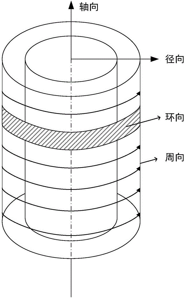
[0135] Specifically, the above-mentioned multiple ultrasonic transducers in the same circular direction form an ultrasonic circular transducer array. In this implementation, the ultrasonic hoop transducer array is arranged coaxially with the annular target area, and the ultrasonic hoop transducer array is used to emit non-focused plane waves and receive ultrasonic echo signals, so that the ultrasonic hoop transducer array The cross-sectional imaging of the target area in the axial direct...

Embodiment 3

[0149] Such as Figure 10 As shown, the present embodiment provides a method for ultrasonic elastography, comprising the following steps:

[0150] S31: Use multiple annular ultrasonic transducer arrays coaxially connected in series to transmit non-focused ultrasonic plane waves to the target area to obtain initial ultrasonic echo signals at different circumferential positions of the target area, and the annular ultrasonic transducer array is also set For multiple ultrasonic transducers on the same ring, the target area includes a circular target area, or a non-closed arc target area;

[0151] S32: Transmitting a shear wave excitation beam along at least one radial direction of the target area, such as Figure 11 shown;

[0152] S33: using a plurality of circular ultrasonic transducer arrays to transmit non-focused ultrasonic plane waves to the target area to obtain ultrasonic echo signals at different circumferential positions of the target area after the shear wave is gener...


PUM


Abstract

The invention provides an ultrasonic beam synthesizing method, an ultrasonic imaging method and an ultrasonic elastography method and belongs to the technical field of ultrasonics. The ultrasonic beam synthesizing method includes: acquiring distances between at least two tandem ultrasonic transducer arrays and a target focus point and initial wave velocity of ultrasonic waves in a target area; according to the distances between the transducer arrays and the target focus point and the initial wave velocity, acquiring initial transmitting parameters of each transducer array; transmitting ultrasonic beams according to the initial transmitting parameters corresponding to the transducer arrays and receiving ultrasonic echo signals by the transducer arrays; judging whether the ultrasonic beams transmitted by each transducer array focus at the target focus point or not according to the ultrasonic echo signals; if yes, transmitting ultrasonic beams according to the corresponding initial transmitting parameters by each ultrasonic transducer array to form a pulse beam focusing the target focus point. By utilizing the ultrasonic beam synthesizing method, ultrasonic beam energy is increased, and the beams transmitted by each transducer array are ensured to accurately focus the target focus point.

Description

technical field [0001] The invention relates to the field of ultrasonic technology, in particular to an ultrasonic beam synthesis method, an ultrasonic imaging method and an ultrasonic elastic imaging method. Background technique [0002] When multiple ultrasonic transducers or multiple ultrasonic transducer arrays are actually used to form a focused ultrasonic beam, the position between each ultrasonic transducer or each ultrasonic transducer array may change due to bending deformation and other reasons. As a result, the orientation of the transducer or transducer array changes, or the propagation speed of the ultrasonic wave at different positions is inconsistent due to the inconsistency of the composition and structure of the target area. All of the above factors may cause each transducer or transducer array to emit ultrasonic waves according to its preset fixed emission parameters, which may fail to focus on the target focal point. Using unqualified pulse wave velocity ...

Claims


Application Information

Patent Timeline
IPC IPC(8): G01S7/52G01S15/89G10K11/34
CPCG10K11/34G10K11/346G01S7/52G01S15/89A61B8/4494A61B8/485G01S7/52042
Inventor 焦阳崔崤峣顾天明简小华徐杰
Owner SUZHOU INST OF BIOMEDICAL ENG & TECH CHINESE ACADEMY OF SCI
Learn More