
Paving method of assembled base asphalt pavement

An asphalt pavement, combined technology, applied in the direction of roads, roads, coagulation pavement paved on site, etc., to achieve the effect of tight bonding, reducing attenuation rate, and avoiding bottom voids

Active Publication Date: 2019-06-28
佛山市公路桥梁工程监测站有限公司 +2
View PDF6 Cites 8 Cited by
  • Summary
  • Abstract
  • Description
  • Claims
  • Application Information

AI Technical Summary

Problems solved by technology

On the other hand, the shrinkage cracking of the semi-rigid base and the resulting reflective cracks in the asphalt pavement are common, causing early damage to the pavement structure, and periodic overhaul and reconstruction cause huge waste of resources and pressure on funds and environmental protection

Method used


Image

  • Paving method of assembled base asphalt pavement
  • Paving method of assembled base asphalt pavement
  • Paving method of assembled base asphalt pavement

Examples


Embodiment

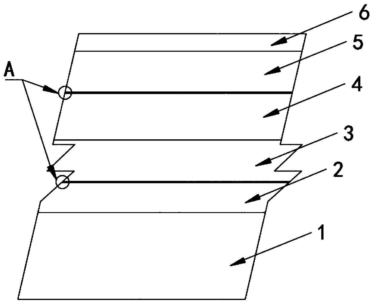
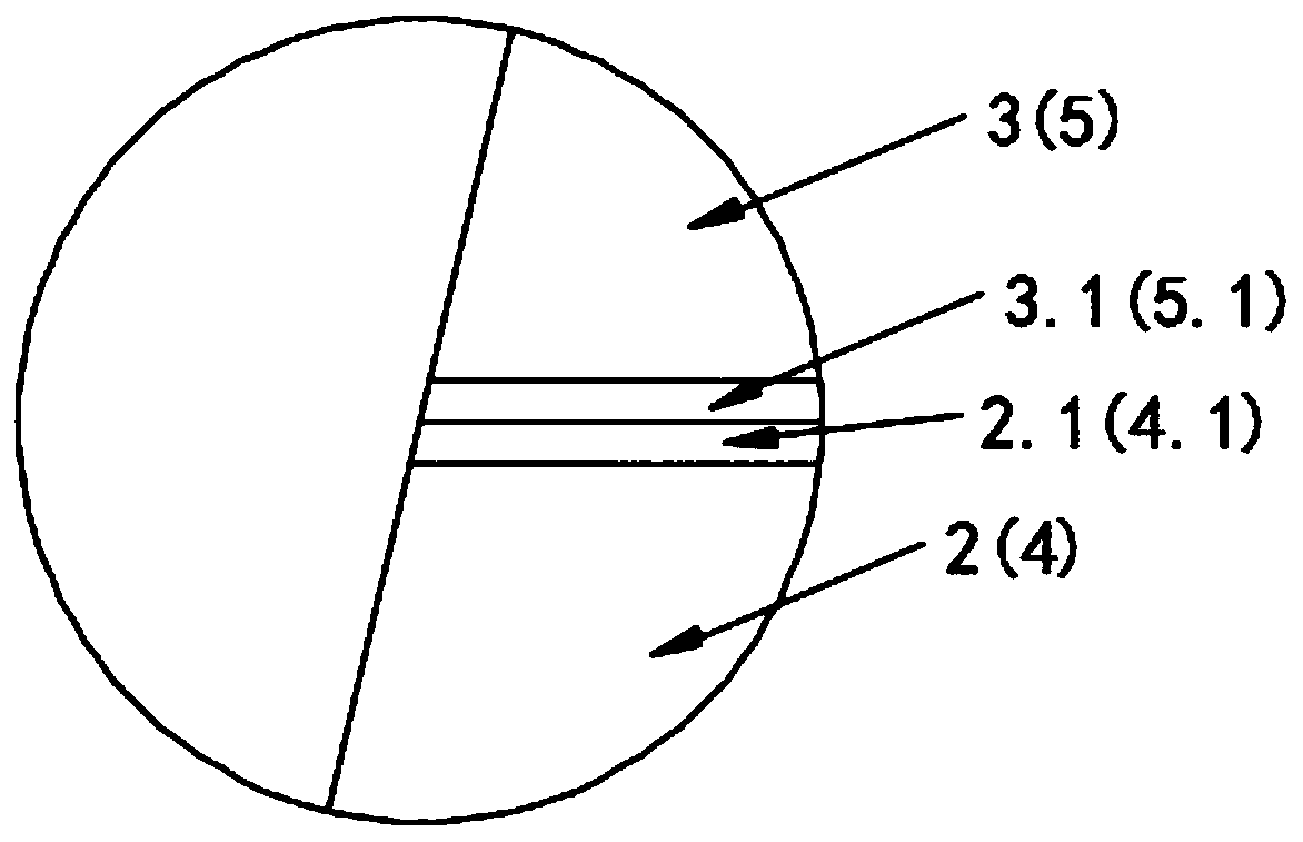
[0051] as attached figure 1 As shown, the combined base asphalt pavement paving method of this embodiment consists of an asphalt mixture viscoelastic anti-fatigue cushion layer 3, a cement-stabilized gravel lower base 4, an asphalt-stabilized upper base 5, and an asphalt surface layer 6. Asphalt mixture viscoelastic anti-fatigue buffer cushion layer 3, cement-stabilized crushed stone lower base layer 4, asphalt-stabilized upper base layer 5, and asphalt surface layer 6 are directly paved on the roadbed from bottom to top. The roadbed includes a soil foundation 1 and a cement-improved soil layer 2 on top of the soil foundation 1 .

[0052] 1. Cement improves soil

[0053] 1. Raw material indicators

[0054]Cement-improved soil layers should use gravel soil with better grading as subgrade filler, with a maximum particle size of 53 mm, a soil uniformity coefficient of 13, a liquid limit of 35, a plasticity index of no more than 10, and a soil with an organic matter content of l...

experiment example

[0116] Using the current asphalt pavement design specification method and the MEPDG mechanical experience method to carry out structural checking and analysis on the two pavements of Example 1 and Comparative Example:

[0117] 1. Based on the American MEPDG calculation and analysis method

[0118] Select the measured structure and material parameters, as attached image 3 As shown, the cracking rate of the traditional pavement structure (comparative example) from the bottom of the pavement to the top of the pavement increases exponentially with time:

[0119] y=0.0505e 0.008x Where y is the cracking rate and x is the time (months).

[0120] And the pavement structure of the present invention is by the equation of time-varying smooth rate of cracking from the bottom of the pavement to the top of the pavement: y=0.0001x-0.0064 where y is the cracking rate, and x is the time (number of months), and the probability of cracking is almost zero.

[0121] 2. Calculation and analys...


PUM

PropertyMeasurementUnit
penetration depthaaaaaaaaaa
stabilityaaaaaaaaaa
thicknessaaaaaaaaaa

Abstract

The invention discloses a paving method of assembled base asphalt pavement, and belongs to the technical field of road pavement. A pavement structure comprises a base layer structure and an asphalt face layer and is characterized in that the base layer structure is formed by an asphalt mixed material viscoelastic anti-fatigue buffering cushion layer, a semi-rigid lower base layer and semi-rigid upper base layer, and the elastic anti-fatigue buffering cushion layer, the semi-rigid lower base layer and the semi-rigid upper base layer are laid on a roadbed from bottom to top. Compared with the prior art, the paving method of the pavement structure comprises the step that the asphalt mixed material viscoelastic anti-fatigue buffering cushion layer is arranged under the semi-rigid base layers,and thus damage of the semi-rigid base layers caused by cavities in the roadbed and uneven stress is reduced; meanwhile, the anti-fatigue performance of the semi-rigid base layers is improved; the upper base layer is arranged on the semi-rigid lower base layer, so that the reflection crack resistance capability of the pavement structure is improved, the service life of the pavement structure is greatly prolonged, and structural damage of the pavement in a short period is effectively avoided; besides, the thickness of the semi-rigid base layer is also reduced, and consumption of building materials such as cement and gravel is reduced.

Description

technical field [0001] The invention relates to the field of pavement pavement, in particular to a method for paving a combined base asphalt pavement. Background technique [0002] More than 90% of asphalt pavement bases and subbases of high-grade highways in my country use semi-rigid materials. In the future construction of high-grade highways in China, semi-rigid base materials will still become the main material of pavement bases. On the one hand, the semi-rigid base has strong integrity and is highly sensitive to axle loads for heavy-duty traffic. Under the uneven and repeated action of heavy axle loads, the strength and modulus of semi-rigid base materials will be affected by dry-wet and freeze-thaw cycles and Under the action of repeated loads, it will gradually attenuate due to fatigue, and the uneven stress on the semi-rigid base will gradually change from the whole block to large blocks, small blocks, and fragments. On the other hand, the shrinkage cracking of the ...

Claims


Application Information

Patent Timeline
Patent Type & Authority Applications(China)
IPC IPC(8): E01C1/00E01C7/32C04B26/26
Inventor 闫翔鹏郭立成韦金城曾国东王林周敏安平马士杰季正军孟令军杨永前袁玉波张晓萌魏磊王光勇
Owner 佛山市公路桥梁工程监测站有限公司
Learn More