Pressure relief joint and liquid cooling component using same
A technology of crimping joints and components, which is applied in the direction of engine components, cooling/ventilation/heating transformation, safety valves, etc., and can solve problems such as the inability to ensure the sealing of liquid cooling components in the box and the decrease in spring elasticity
- Summary
- Abstract
- Description
- Claims
- Application Information
AI Technical Summary
Problems solved by technology
Method used
Image
Examples
specific Embodiment 1
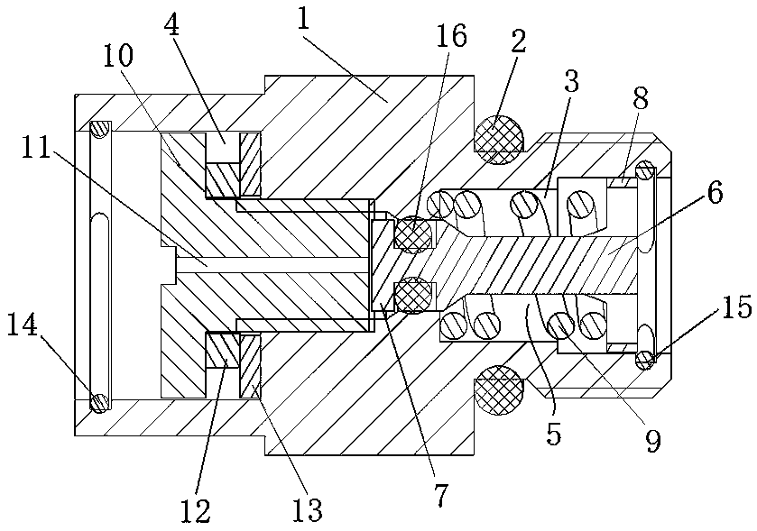
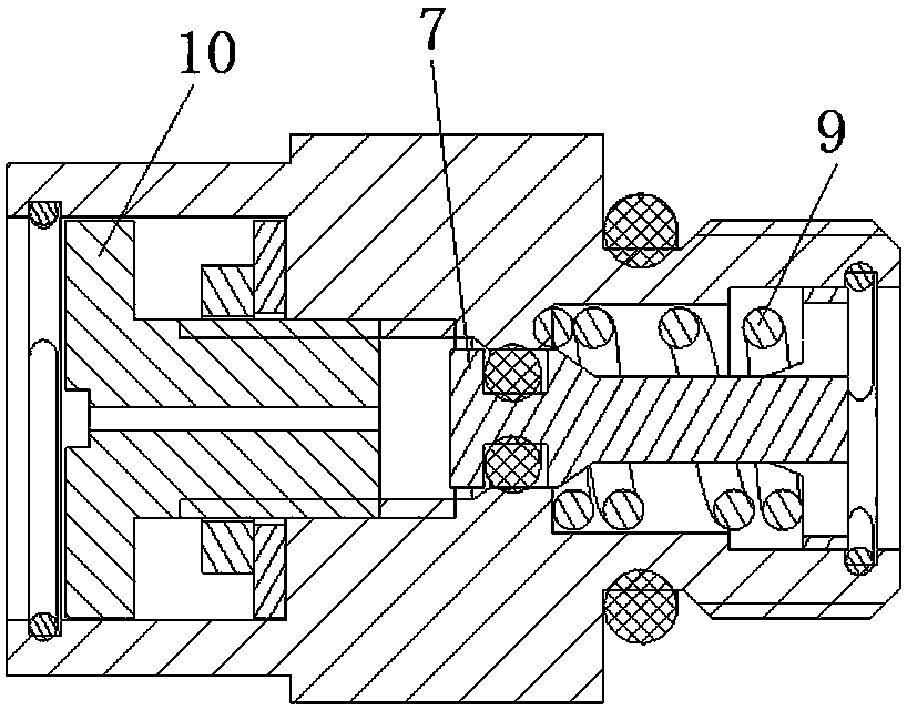
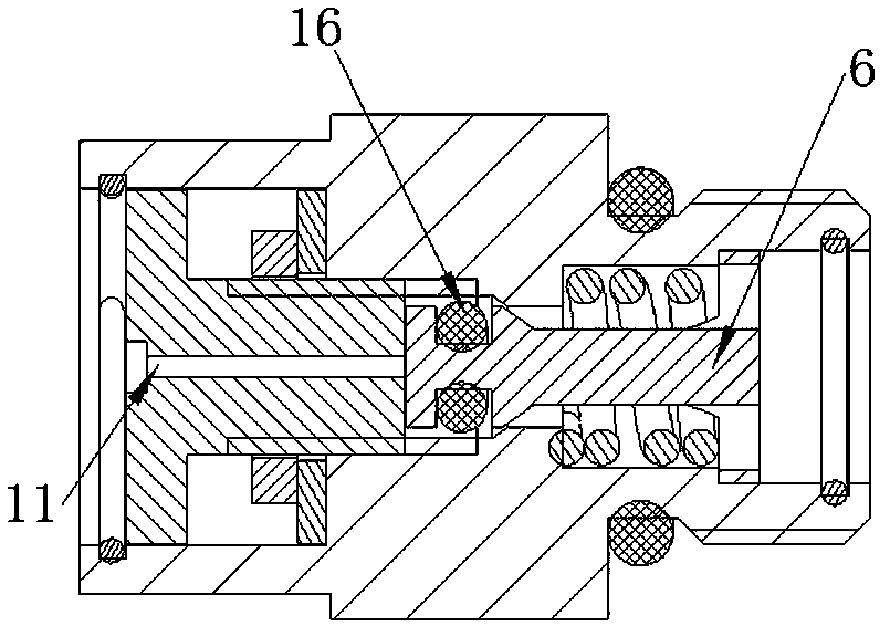
[0027] Such as Figure 1 to Figure 3 As shown, the pressure relief joint includes a joint seat 1, and the outside of the right end of the joint seat 1 along the axial direction is provided with threads for assembling on the coolant cavity, and a housing sealing ring 2 is installed on the joint seat 1 to prevent the coolant from The coolant in the cavity flows out through the pressure relief joint to ensure the airtightness of the coolant cavity.
[0028] The joint seat 1 has an axial through hole for communicating with the coolant cavity, and the axial through hole includes a valve core installation section 3 for installing a valve core and a screw installation section 4 for installing a locking screw. The spool installation section 3 includes a spring installation section with a larger aperture and a spool sealing section with a smaller aperture. A pressure relief spool 5 is installed along the axial movement guide in the spool installation section 3. The pressure relief spoo...
specific Embodiment 2
[0036] Such as Figure 4 As shown, the difference from Embodiment 1 is that in this embodiment, a blocking rod 17 is installed radially on the joint seat 1, and the way that the blocking rod 17 is assembled on the joint seat 1 can be threaded installation or other activities. way of installation. Figure 4 In the process, the blocking rod 17 and the pressure relief valve core 5 stop and cooperate to prevent the pressure relief valve core 5 from continuing to move to the left for pressure relief. When debugging or transporting the liquid-cooled component, or when the liquid-cooled component is in a high-temperature working environment, in order to prevent the pressure of the coolant inside the liquid-cooled component from increasing sharply and not being released. The retaining rod 17 is removed from the left end of the pressure relief spool 5, and the pressure relief spool 5 can perform normal pressure relief and blocking.
[0037] In this embodiment, the blocking rod 17 con...
PUM
 Abstract
Description
Claims
Application Information
 - R&D Engineer
- R&D Manager
- IP Professional
- Industry Leading Data Capabilities
- Powerful AI technology
- Patent DNA Extraction
Browse by: Latest US Patents, China's latest patents, Technical Efficacy Thesaurus, Application Domain, Technology Topic, Popular Technical Reports.
© 2024 PatSnap. All rights reserved.Legal|Privacy policy|Modern Slavery Act Transparency Statement|Sitemap|About US| Contact US: help@patsnap.com


