
Rolling bearing composite fault determining method and terminal device

A rolling bearing and composite fault technology, applied in the field of bearing composite fault separation, can solve the problems of complex vibration signals and difficulty in diagnosing composite faults of rolling bearings of wind turbines, and achieve the effect of suppressing noise.

Inactive Publication Date: 2019-06-21
NORTH CHINA ELECTRIC POWER UNIV (BAODING)
View PDF3 Cites 2 Cited by
  • Summary
  • Abstract
  • Description
  • Claims
  • Application Information

AI Technical Summary

Problems solved by technology

Composite fault refers to a fault in which multiple faults occur simultaneously in rotating machinery and all fault features are coupled together. The composite fault signal is not a simple superposition of a single fault signal, but the fault features of different components are mixed and interfere with each other, making the vibration signal It is more complicated, so it brings great difficulty to the composite fault diagnosis of wind turbine rolling bearings

Method used


Image

  • Rolling bearing composite fault determining method and terminal device
  • Rolling bearing composite fault determining method and terminal device
  • Rolling bearing composite fault determining method and terminal device

Examples


Embodiment Construction

[0054]In the following description, specific details such as specific system structures and technologies are presented for the purpose of illustration rather than limitation, so as to thoroughly understand the embodiments of the present invention. It will be apparent, however, to one skilled in the art that the invention may be practiced in other embodiments without these specific details. In other instances, detailed descriptions of well-known systems, devices, circuits, and methods are omitted so as not to obscure the description of the present invention with unnecessary detail.

[0055] In order to illustrate the technical solutions of the present invention, specific examples are used below to illustrate.

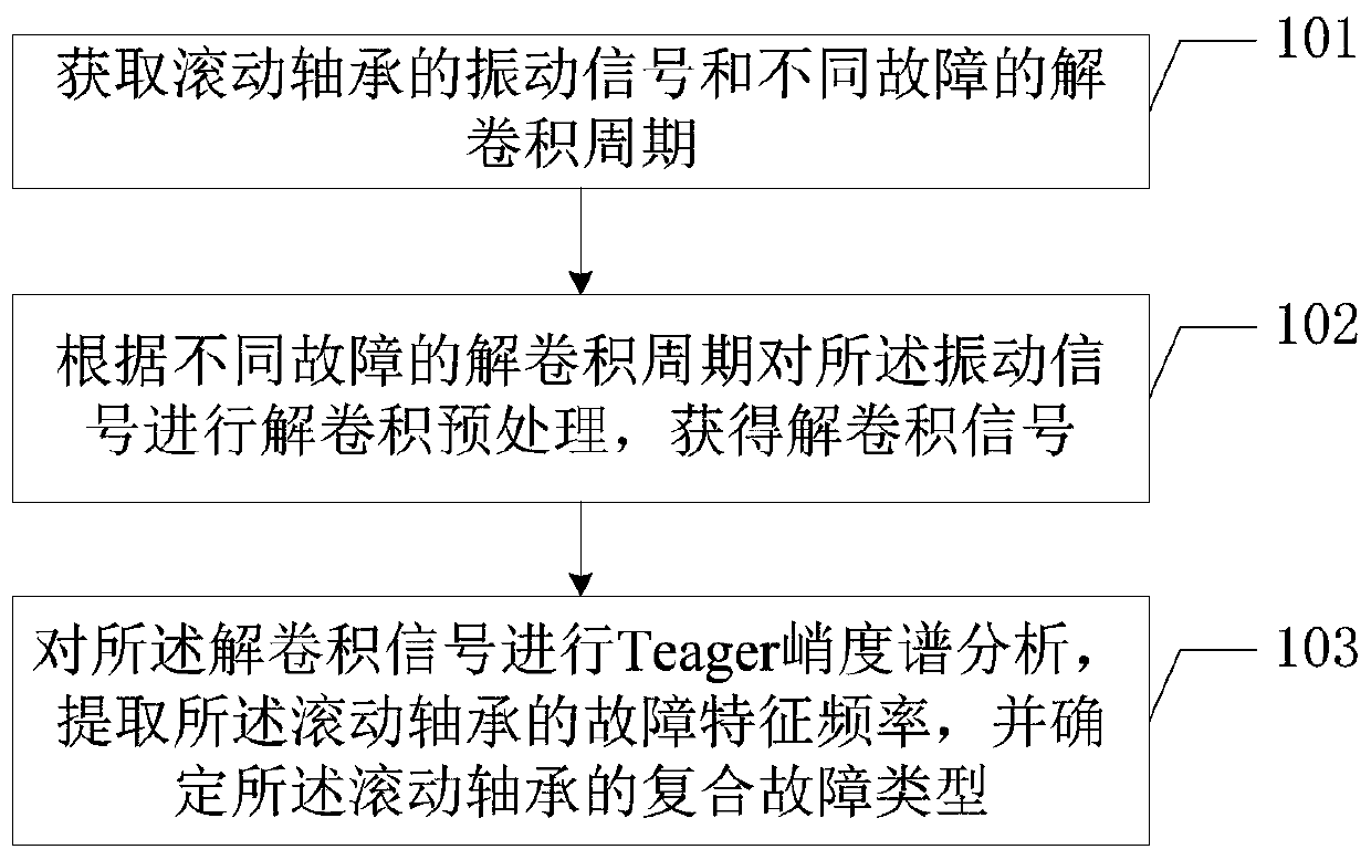
[0056] figure 1 It is a schematic flowchart of a method for determining a complex fault of a rolling bearing provided in an embodiment of the present invention, and is described in detail as follows.

[0057] Step 101, acquiring vibration signals of rolling bearings an...


PUM


Abstract

The invention is applicable to the technical field of bearing composite fault separation, and provides a rolling bearing composite fault determining method and a terminal device. The method comprisessteps: a vibration signal of the rolling bearing and a deconvolution period of a different fault are acquired; the vibration signal is subjected to deconvolution processing according to the deconvolution period of a different fault to obtain a deconvolution signal; the deconvolution signal is subjected to Teager kurtosis spectrum analysis, a fault characteristic frequency of the rolling bearing isextracted, the composite fault type of the rolling bearing is determined, a single fault source signal in a mixed signal can be separated and extracted clearly and accurately, hidden weak feature information is effectively amplified and extracted, and thus, the rolling bearing state can be distinguished comprehensively and accurately.

Description

technical field [0001] The invention belongs to the technical field of bearing composite fault separation, and in particular relates to a method for determining a rolling bearing composite fault and a terminal device. Background technique [0002] In recent years, wind energy, as a renewable energy source, has received more and more attention worldwide. However, the working environment of wind turbines is harsh, the wind is unstable, and the load fluctuates in a large range, which is prone to failure. Rolling bearings are one of the key components of rotating machinery and are widely used in wind turbines. According to statistics, in the rotating machinery using rolling bearings, about 30% of the mechanical failures are caused by rolling bearings, and in the actual operation of wind turbines, failures often do not appear alone, and one failure often causes other failures occurrence, and then a state where multiple faults coexist. Composite fault refers to a fault in which...

Claims


Application Information

Patent Timeline
Patent Type & Authority Applications(China)
IPC IPC(8): G01M13/045
Inventor 向玲李营胡爱军刘随贤王朋鹤安朝辉
Owner NORTH CHINA ELECTRIC POWER UNIV (BAODING)
Learn More