Damping type current-carrying overall dropper

An overall, current-carrying technology, applied in the direction of power lines, overhead lines, transportation and packaging, etc., can solve the problems of high resistivity, loss of damping function of the device, loss of damping function, etc., to improve service life, reasonable and feasible structure, improve holistic effect

Pending Publication Date: 2019-06-21
张国康
View PDF1 Cites 0 Cited by
  • Summary
  • Abstract
  • Description
  • Claims
  • Application Information

AI Technical Summary

Problems solved by technology

[0003] Existing integral current-carrying hanging strings comprise contact wire hanging string clips, catenary cable hanging string clips; figure 1 ); the damping body body in the invention patent with the patent document number (CN101559730B) is a high damping rubber body, and its disadvantages are: the rubber material is easy to age, loses elasticity, and loses the damping function, so that the entire device loses the damping function
Wrapped in the inside of the steel strand, that is, wrapped by the steel wires of the steel strand unit and twisted twice. When working, the gap changes continuously. Under the condition of 27.5kV high voltage and high current, discharge phenomenon will occur, and the hanging string will be blown; the material of the hanging string in the invention patent with the patent document number (CN101559730B) is steel Quality stranded wire, its disadvantage is: large resistivity, large power loss, easy to break; the patent document number is (CN101559730B) In the invention patent, suspension string anchor bolts are set, and its disadvantage is: compared with the reliable connection of this structure sex will get worse

Method used


Image

  • Damping type current-carrying overall dropper
  • Damping type current-carrying overall dropper
  • Damping type current-carrying overall dropper

Examples


Embodiment Construction

[0018] The structural principle and working principle of the present invention will be further described in detail below in conjunction with the drawings and embodiments.

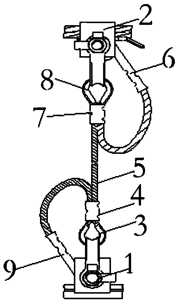
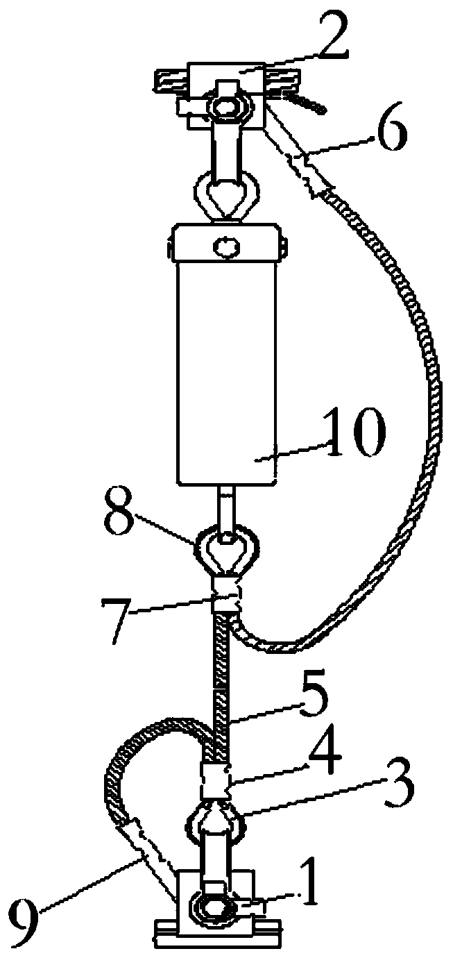
[0019] see figure 2 , a damping type current-carrying integral hanging string, including a lower contact wire hanging string clip 1 and an upper catenary cable hanging string clip 2; the contact wire hanging string clip 1 passes through a heart ring-3 and a crimping tube- 4 is connected with the lower part of the hanging string 5; the lower end of the hanging string 5 is connected with the terminal one 9; The tension cable hanging string clip 2 is connected; the upper end of the hanging string 5 is connected to the upper terminal 2 6; a damping device 10 is arranged between the dead cable hanging string clip and the heart ring two; the damping device The connecting earrings at the two ends are respectively connected with the suspension string clamp of the bearing cable and the heart ring two.

[0020] Th...


PUM


Abstract

A damping type current-carrying overall dropper which includes a lower contact line dropper cable clamp and an upper carrier cable dropper cable clamp, wherein the contact line dropper cable clamp isconnected with the lower part of the dropper line through a capel I and a compression connecting pipe I; the lower end socket of the dropper line is further connected with a terminal I; the upper partof the dropper line is connected with a compression connecting pipe II and a capel II, and then the capel II is connected with the carrier cable dropper cable clamp; the upper end socket of the dropper line is then connected with an upper the terminal II; a damping device is arranged between the carrier cable dropper cable clamp and the capel II, and is respectively connected with the carrier cable dropper cable clamp and the capel II through connecting lugs at the two ends of the damping device. Through the upper cable clamp and the lower cable clamp, the contact line dropper cable clamp andthe carrier cable dropper cable clamp, and the damping device, the damping type current-carrying overall dropper is mounted between bearing cables and contact wires, the contact wires are overhung, so that the dropper is kept with consistent height and elasticity, enables the bearing cables and the contact wires to play the current guiding function for an engine, and has the characteristics of reasonable and feasible structure, easiness in manufacture, convenience in installation and long service life.

Description

technical field [0001] The invention belongs to the technical field of suspension strings for electrified railways, and in particular relates to a damping type current-carrying integral suspension string. Background technique [0002] The crimping integral hanging string used in the catenary of medium and high-speed electrified railways has adopted German catenary technology since the Harbin-Dalian line in 1999. During the operation of the previous 160km / h speed-up line Jingqin line for more than 10 years, the status It is still stable, but since the 200km / h speed line, especially the 300km / h speed section of the first trunk high-speed rail Wuhan-Guangzhou line was opened in 2008, it has only been in operation for 5 years, and most sections have overall current-carrying suspension strings The phenomenon of broken wires, broken strands, or even broken ropes is too far from the 20-year requirement for an overhaul cycle under the conventional practice. These phenomena also app...

Claims


Application Information

Patent Timeline
IPC IPC(8): B60M1/234B60M1/20
Inventor 张国康
Owner 张国康
Why Eureka
Try Eureka