
Sweeping machine

A sweeping machine and machine technology, applied in the field of sweeping machines, can solve the problems of low sweeping accuracy of glass sheets, difficulty in ensuring product quality, and low processing efficiency, so as to achieve good sweeping effect, shorten sweeping time, The effect of improving efficiency

Pending Publication Date: 2019-06-18
东莞市力优机械设备有限公司
View PDF0 Cites 5 Cited by
  • Summary
  • Abstract
  • Description
  • Claims
  • Application Information

AI Technical Summary

Problems solved by technology

There are two main types of existing sweeping machines, one is the non-turning lifting sweeping machine, which installs the corresponding jig for placing glass sheets on the lower grinding table, and the upper grinding table descends and rotates with the lower grinding table. With the assistance of the sweeping liquid, the sweeping process of the glass sheet is completed. Although the structure of this sweeping machine is relatively stable, the processing efficiency is low; the other is a reversible lifting sweeping machine, and there are two upper Grinding discs, so that one upper grinding disc faces up and the other upper grinding disc faces downwards. After placing the glass piece on the upward grinding disc, the two upper grinding discs are turned over 180°, so that the two upper grinding discs are exchanged, and then pass through the lower grinding disc and the downward grinding disc. The upper grinding disc is used to sweep the glass sheet. Although this sweeping machine has high processing efficiency, its structure is unstable, and the scanning accuracy of the glass sheet is low, so it is difficult to guarantee the quality of the product.

Method used


Image

  • Sweeping machine
  • Sweeping machine
  • Sweeping machine

Examples


Embodiment Construction

[0025] In order to facilitate the understanding of those skilled in the art, the present invention will be further described below in conjunction with the embodiments and accompanying drawings, and the contents mentioned in the embodiments are not intended to limit the present invention.

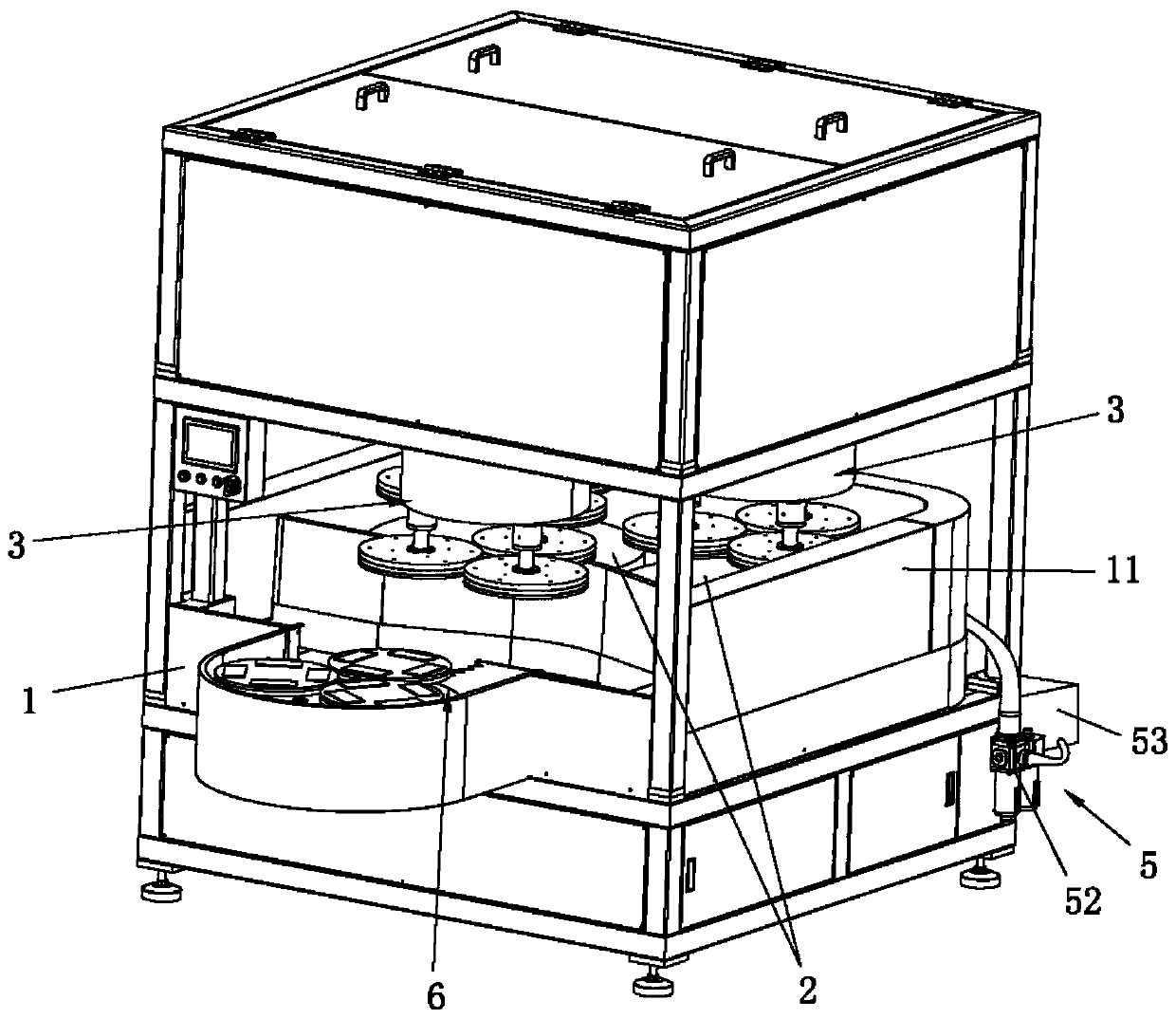
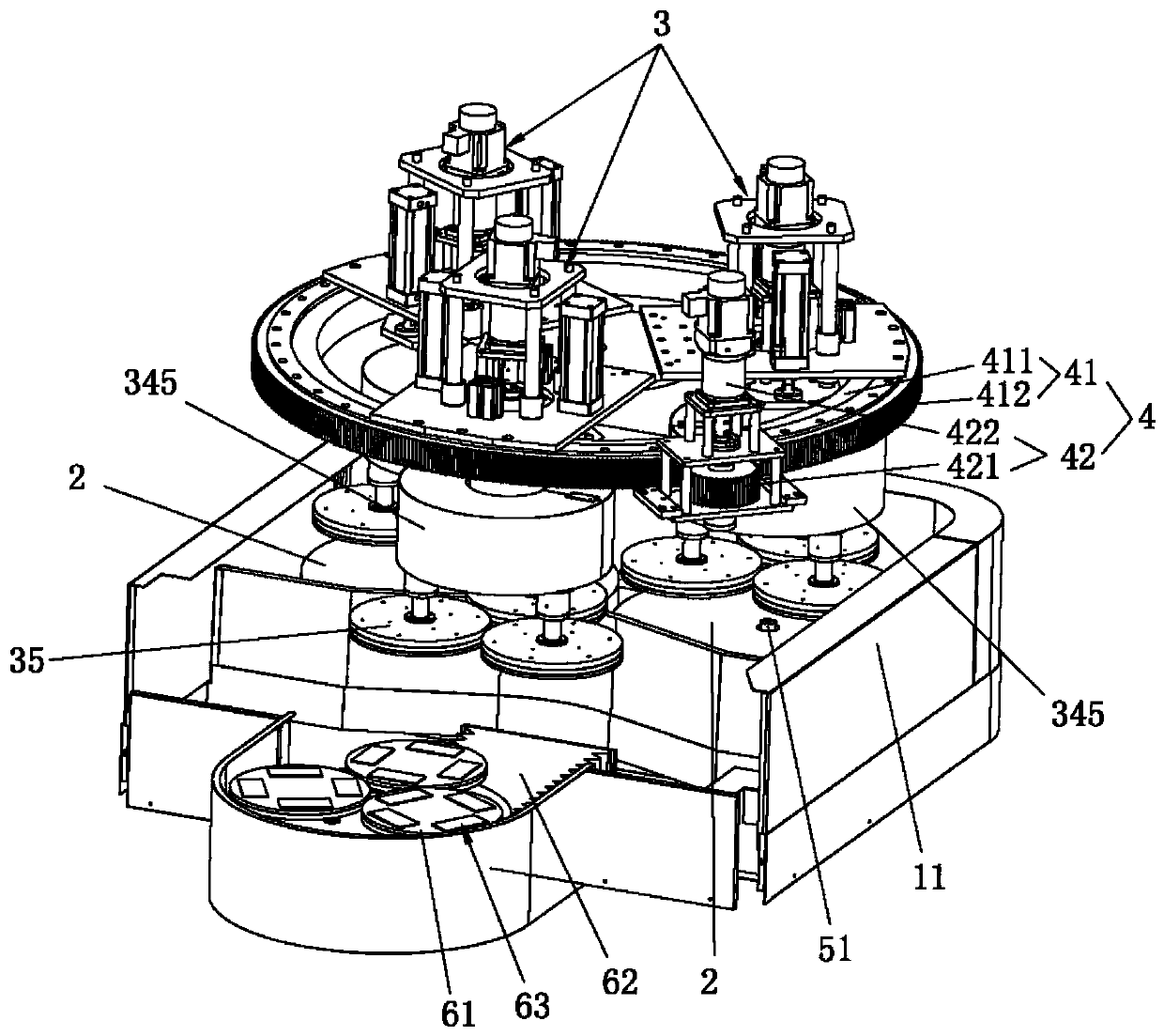
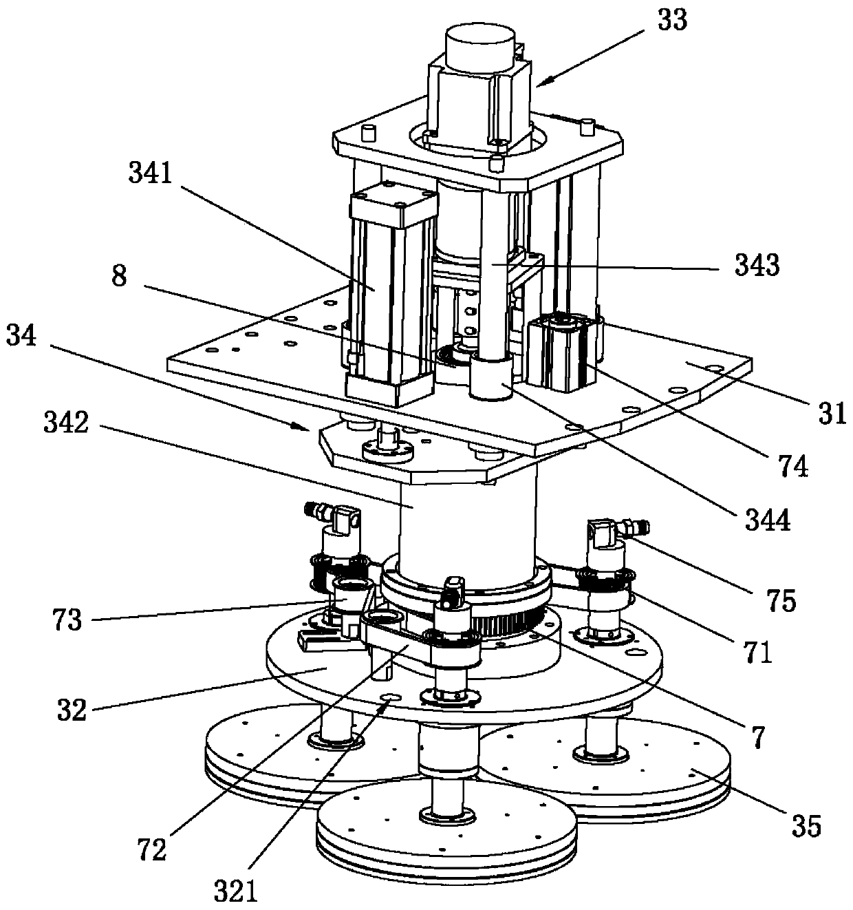
[0026] like Figure 1 to Figure 7 As shown, a light sweeping machine provided by the present invention includes a light sweeping machine 1, at least two lower grinding discs 2 which are rotatably arranged on the working surface of the light sweeping machine 1, arranged on the light sweeping machine 1 and connected with the lower The grinding disc 2 cooperates with a plurality of upper grinding disc devices 3 for sweeping the material and a conversion drive mechanism 4 for driving a plurality of upper grinding disc devices 3 to convert positions. The middle part is also used for supplying the required liquid supply device 5 for sweeping liquid when sweeping materials. The upper grinding disc ...


PUM


Abstract

The invention relates to the technical field of sweeping equipment, in particular to a sweeping machine. The sweeping machine comprises a sweeping machine table, at least two lower grinding discs, a plurality of upper grinding disc devices and a conversion driving mechanism, wherein the upper grinding discs are matched with the lower grinding discs and used for sweeping materials, the conversion driving mechanism is used for driving the positions of the multiple upper grinding disc devices to be switched, and a liquid supply device used for supplying sweeping liquid is arranged in the middle of the lower grinding discs; and each upper grinding disc device comprises a grinding disc seat, a rotating disc, a rotating driving mechanism, a lifting driving mechanism and a plurality of upper grinding discs, the rotating disc is rotationally arranged on the grinding disc seat, the rotating driving mechanism is used for driving the rotating disc to rotate, the lifting driving mechanism is usedfor driving the rotating disc to be close to or far away from the lower grinding disc, the upper grinding discs are rotationally arranged on the rotating disc, and the upper grinding discs are provided with a plurality of material sucking cavities used for containing the materials. According to the sweeping machine, the time for material-sweeping is shortened, the material-sweeping efficiency is improved, the production cost is reduced, the diffusion of the sweeping liquid is stable and uniform, the rotating disc and the upper grinding disc in a combined mode, the sweeping effect is good, andthe precision of material sweeping is improved.

Description

technical field [0001] The invention relates to the technical field of light sweeping equipment, in particular to a light sweeping machine. Background technique [0002] The light sweeping machine is mainly used to process mobile phone glass screens, lenses and other products. Existing light sweeping machines all adopt upper grinding disc and lower grinding disc to cooperate to process glass sheet. There are two main types of existing sweeping machines, one is the non-turning lifting sweeping machine, which installs the corresponding jig for placing glass sheets on the lower grinding table, and the upper grinding table descends and rotates with the lower grinding table. With the assistance of the sweeping liquid, the sweeping process of the glass sheet is completed. Although the structure of this sweeping machine is relatively stable, the processing efficiency is low; the other is a reversible lifting sweeping machine, and there are two upper Grinding discs, so that one up...

Claims


Application Information

Patent Timeline
IPC IPC(8): B24B29/02B24B27/00B24B57/02
Inventor 罗路南劳伟洪
Owner 东莞市力优机械设备有限公司
Learn More