
Insulation fault positioning device and method applied to insulated tubular busbar

A technology of insulation faults and insulating tubes, applied in the field of fault location of insulating tubular busbars, which can solve the problems of fluctuations and the influence of on-site environmental factors, single monitoring means, and the inability to accurately grasp the insulation status of insulating tubular busbars, etc., to achieve fast and accurate positioning instructions , Reduce the effect of dielectric loss measurement error

Active Publication Date: 2019-06-14
STATE GRID HUBEI ELECTRIC POWER RES INST +2
View PDF6 Cites 7 Cited by
  • Summary
  • Abstract
  • Description
  • Claims
  • Application Information

AI Technical Summary

Problems solved by technology

Due to the lack of existing monitoring methods, the original method of calculating dielectric loss with PT as a reference is easily affected by line frequency fluctuations and site environmental factors, resulting in the insulated tubular busbar being in operation. The insulation status cannot be accurately grasped; different parts of the insulating tubular busbar appear When an insulation fault occurs, the current value may change dynamically in the range of several milliamps or hundreds of amperes, which puts forward high technical requirements for the monitoring device; at the same time, how to quickly and accurately indicate the insulation fault location of the insulating tubular busbar, there are still many problems. insufficient
In summary, none of the existing insulation monitoring methods can be directly applied to insulation fault location devices for insulating tubular busbars.

Method used


Image

  • Insulation fault positioning device and method applied to insulated tubular busbar

Examples


Embodiment Construction

[0036] The technical solutions in the present invention will be clearly and completely described below in conjunction with the accompanying drawings in the present invention.

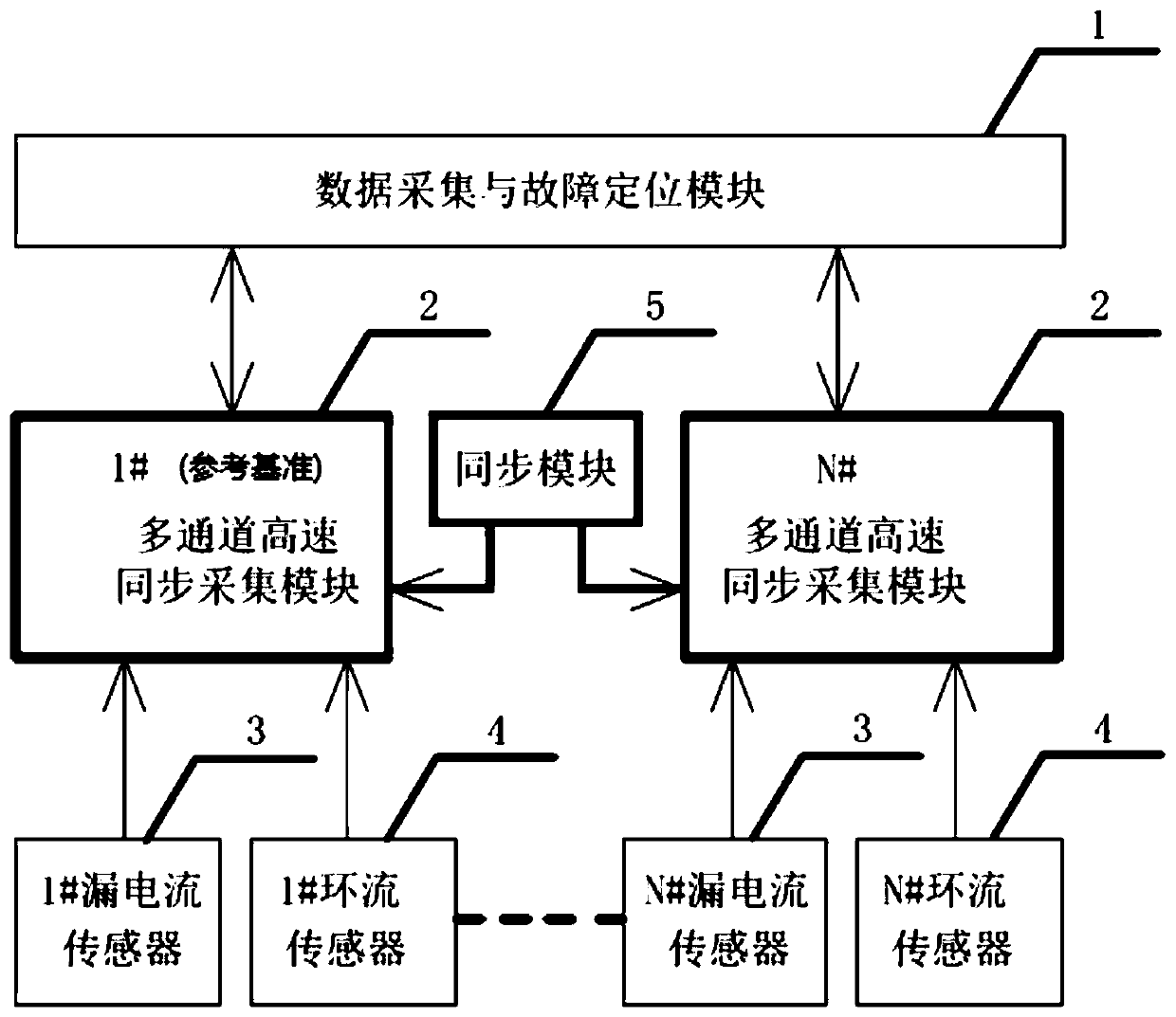
[0037] Such as figure 1 As shown, the present invention provides a device for insulation fault location of insulating tubular busbars, including a leakage current sensor 3 , a circulating current sensor 4 , a multi-channel high-speed synchronous acquisition module 2 , a data acquisition and fault location module 1 , and a synchronization module 5 .

[0038] The leakage current sensor 3 is installed under the grounding down conductor of each section of the insulating tubular busbar ground screen, and uses the principle of current mutual inductance to collect the leakage current of the main insulator of the insulating tubular busbar; the leakage current sensor 3 adopts a multi-layer nested magnetic shield Structural design, which has good anti-electromagnetic interference effect against the strong magneti...


PUM


Abstract

The invention provides an insulation fault positioning device and method applied to an insulated tubular busbar, which is based on the particularity of the segmented series connection laying of the insulated tubular busbar, uses the replacement of an original PT with a section of calibrated insulated busbar as a reference, and can effectively reduce the dielectric loss measurement error introducedby line frequency fluctuations in the online monitoring. The invention judges a dampness fault of a main insulator of each section of insulated tubular busbar by using a relative dielectric loss parameter, and judges a multi-point grounding fault of the outer sheath of each section of insulated tubular busbar by using a circulating current value. The change of the relative dielectric loss parameter of the main insulator of the insulated tubular busbar and the change of the circulating current value of the outer sheath of the insulated tubular busbar are continuously monitored and are comparedwith preset parameter thresholds, and the location having the insulation fault is dynamically marked on an insulated tubular busbar laying line layout schematic diagram; therefore, the fast and accurate positioning of the insulated tubular busbar insulation fault is realized.

Description

technical field [0001] The invention relates to the field of fault location of an insulating tubular busbar, in particular to a device and method for locating insulation faults of a main insulator and an outer sheath of an insulating tubular busbar. Background technique [0002] With the rapid development of the power system, the capacity of the main transformer in the substation continues to increase, and the insulating tubular busbar product is widely used as a product with a transmission current of more than 3000A. At present, how to improve the operational reliability of insulating tubular busbars has become an issue of increasing concern to the power sector. Through the comprehensive monitoring of various parameters of the insulating tubular busbar, it is possible to fully expose whether there is an insulation fault in the tubular busbar, and to enhance the scientificity of the insulation state assessment of the insulating tubular busbar. [0003] In field application,...

Claims


Application Information

Patent Timeline
IPC IPC(8): G01R31/08G01R31/12G01R31/02
Inventor 朱思瑞刘睿阮羚李文佩任想杨帆刘楠康
Owner STATE GRID HUBEI ELECTRIC POWER RES INST
Learn More