Pneumatic proportional valve based on MEMS microfluidic chip

A technology of microfluidic chip and pneumatic proportional valve, which is applied in the direction of valve lift, valve details, valve device, etc., can solve the problems of no proportional adjustment function, complex structure, difficult to control, etc., and achieve stable air pressure, small structure, fast The effect of response speed

Pending Publication Date: 2019-06-14
DUNAN ENVIRONMENT TECH
View PDF5 Cites 0 Cited by
  • Summary
  • Abstract
  • Description
  • Claims
  • Application Information

AI Technical Summary

Problems solved by technology

[0002] Although the proportional control valve in the field of pneumatic control is small in size, low in power consumption and fast in response, it can only realize the switching function. Proportional adjustment, complex structure, difficult to control

Method used


Image

  • Pneumatic proportional valve based on MEMS microfluidic chip
  • Pneumatic proportional valve based on MEMS microfluidic chip
  • Pneumatic proportional valve based on MEMS microfluidic chip

Examples


Embodiment Construction

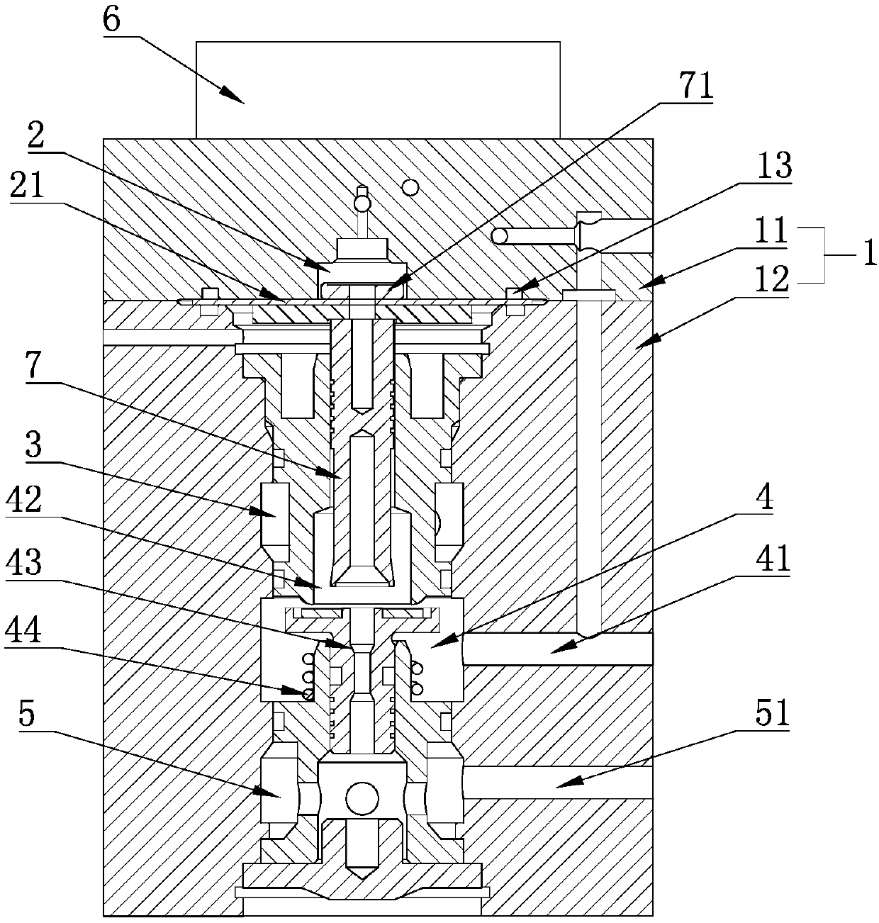
[0026] refer to Figure 1 to Figure 3 An embodiment of a pneumatic proportional valve based on a MEMS microfluidic chip of the present invention will be further described.

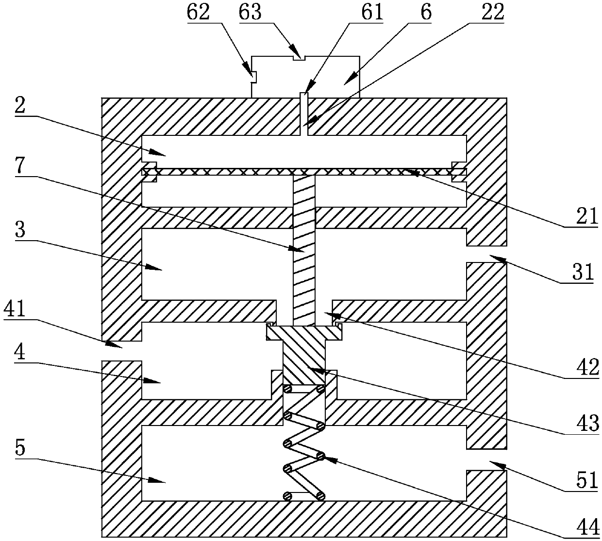
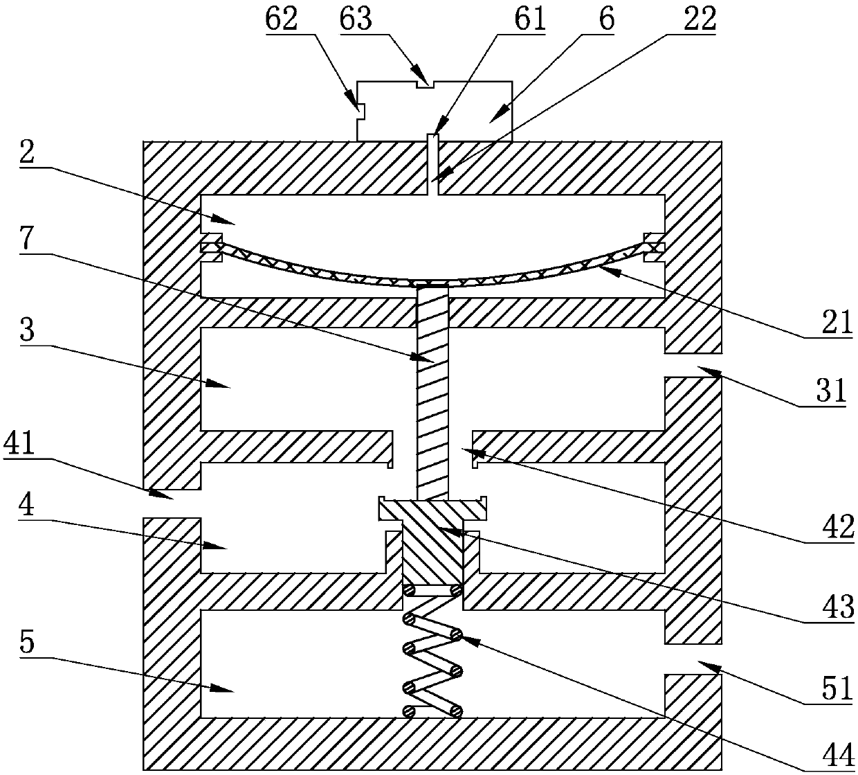
[0027] A pneumatic proportional valve based on MEMS microfluidic chip, such as image 3 As shown, the main valve body 1 and the MEMS microfluidic chip 6 arranged on the main valve body 1 are included, and the MEMS microfluidic chip 6 is provided with a gas source port 62, a control port 61 and an exhaust port 63; the main valve body 1. Diaphragm chamber 2, pressure control chamber 3, air source chamber 4 and exhaust chamber 5 are arranged sequentially from top to bottom. Diaphragm 21 made of rubber is arranged in diaphragm chamber 2, and the middle of diaphragm 21 is connected with The spool 7 moves up and down with the diaphragm 21, the spool 7 passes through the diaphragm 21 and is fixed on the diaphragm 21 by the diaphragm splint 71, and the main valve body 1 is provided with an input connecting the di...


PUM


Abstract

The invention discloses a pneumatic proportional valve based on an MEMS microfluidic chip. The pneumatic proportional valve comprises a main valve body; the main valve body is sequentially provided with a membrane cavity, a pressure control cavity and a gas source cavity from top to bottom; a membrane is arranged in the membrane cavity and connected with a valve element moving up and down along with the membrane; a through hole is formed between the gas source cavity and the pressure control cavity; a valve seat driven by the valve element to open and close the through hole is arranged in thegas source cavity; the MEMS microfluidic chip is arranged on the main valve body and provided with a control opening for outputting gas so as to control the membrane to move; and the control opening communicates with the membrane cavity. Specific pressure output of the control opening can be controlled through the MEMS microfluidic chip so as to control the opening degree of the through hole, thusthe pressure of the gas discharged from the main valve body is controlled, and linear proportional control is achieved, so that the pneumatic proportional valve is small in structure, high in reliability, and wide in application range.

Description

technical field [0001] The invention belongs to the field of pneumatic control, in particular to a pneumatic proportional valve based on a MEMS microfluidic chip. Background technique [0002] Although the proportional control valve in the field of pneumatic control is small in size, low in power consumption and fast in response, it can only realize the switching function. Proportional adjustment, the structure is more complex, difficult to control. Contents of the invention [0003] The technical problem to be solved by the present invention is to provide a pneumatic proportional valve based on a MEMS microfluidic chip with a proportional adjustment function. [0004] In order to solve the above technical problems, the present invention adopts the following technical scheme: a pneumatic proportional valve based on MEMS microfluidic chip, including a main valve body, which is sequentially provided with a diaphragm cavity, a pressure control cavity and a gas valve body fro...

Claims


Application Information

Patent Timeline
Patent Type & Authority Applications(China)
IPC IPC(8): F16K1/00F16K31/126
Inventor 吴昭刘海清方建峰
Owner DUNAN ENVIRONMENT TECH
Why Eureka
Try Eureka