
Fixed constant velocity joint

A constant velocity joint and fixed technology, which is applied in the field of speed joints, can solve the problems of reduced shared load, increased shared load, and reduced durability of fixed constant velocity joints, so as to ease the change of shared load and improve durability.

Inactive Publication Date: 2019-06-14
HONDA MOTOR CO LTD
View PDF7 Cites 0 Cited by
  • Summary
  • Abstract
  • Description
  • Claims
  • Application Information

AI Technical Summary

Problems solved by technology

[0007] If the differential angle of the fixed constant velocity joint increases, then as Image 6 As shown, the size of the gap between the ball and the raceway groove increases or decreases according to the rotation phase, and the load sharing of the balls in the part with a small gap increases, and the load sharing of the balls in the part with a large gap decreases. The problem that the shared load periodically fluctuates with a large amplitude and reduces the durability of the fixed constant velocity joint

Method used


Image

  • Fixed constant velocity joint
  • Fixed constant velocity joint
  • Fixed constant velocity joint

Examples


Embodiment Construction

[0031] Below, based on Figure 1 to Figure 5(B) Embodiments of the present invention will be described.

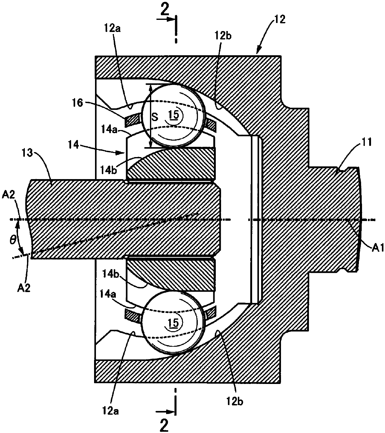
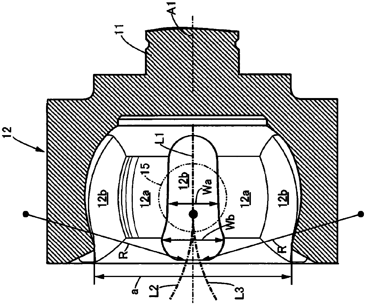
[0032] Such as figure 1 and figure 2 As shown, the fixed constant velocity joint of this embodiment includes an outer member 12 integrally formed with the first rotating shaft 11 and an inner member 14 spline-coupled with the second rotating shaft 13, and the part spherical shape of the inner member 14 The outer peripheral surface 14a of the outer peripheral surface 14a of the first rotary shaft 11 is fitted with a gap with the partially spherical inner peripheral surface 12a of the cup-shaped outer member 12 which is open on the opposite side of the first rotating shaft 11 .

[0033] On the inner peripheral surface 12a of the outer member 12, six inner peripheral track grooves 12b extending in the direction of the axis A1 of the first rotating shaft 11 are formed at intervals of 60° in the circumferential direction. On the outer peripheral surface 14a, six outer peri...


PUM


Abstract

The invention provides a fixed constant velocity joint. In the fixed constant velocity joint, if the differential angle between a rotating shaft of an outer member and a rotating shaft of an inner member becomes large, there is a possibility that the gap between an inner peripheral side raceway groove or an outer peripheral side raceway groove changes according to the rotation phase while the loadsharing of the ball changes and adversely affects the durability. However, the groove width, opposite to one end side, of at least one of the inner peripheral side raceway groove (12b) of the outer member (12) and the outer peripheral side raceway groove(14b) of the inner member (14) is formed broadly relative to the groove width on the other end side, so that even the differential angle (Theta)between the rotation shaft (11) of the outer member (12) and the rotation shaft (13) of the inner member (14) is large, and it is also possible to suppress the gap between the inner peripheral side raceway groove (12b) or the outer peripheral side raceway groove (14b) and the ball (15) from changing depending on the rotation phase, so as to alleviate load sharing changes of the ball (15) and improve the durability.

Description

technical field [0001] The invention relates to a fixed constant velocity joint (joint), which comprises: an outer member, a plurality of inner circumferential track grooves are formed on the inner peripheral surface; an inner member is arranged on the The inside of the outer member, and a plurality of outer peripheral side raceway grooves respectively facing the inner peripheral side raceway grooves are formed on the outer peripheral surface; balls are used to straddle the inner peripheral side raceway grooves and the said inner peripheral side raceway grooves facing each other. and a retainer (retainer) for retaining the ball in the inner peripheral raceway groove and the outer periphery The specified position of the side raceway groove. Background technique [0002] A fixed type constant velocity joint is known from the following Patent Document 1 in which, in order to prevent the angle (that is, the differential angle) formed by the rotation axis of the outer member and...

Claims


Application Information

Patent Timeline
Patent Type & Authority Applications(China)
IPC IPC(8): F16D3/223
Inventor 胜政喜和
Owner HONDA MOTOR CO LTD
Learn More