Eureka AIR delivers breakthrough ideas for toughest innovation challenges, trusted by R&D personnel around the world.

Machining device for sheet cathode electrolyte direct injection machining large-lead nut and machining method of device

A catholyte and processing device technology, applied in the direction of electric processing equipment, electrochemical processing equipment, accessory devices, etc., can solve problems such as difficult to wash away electrolytic products, affect processing speed and stability, and large loss of kinetic energy of electrolyte, etc. Achieve the effects of stable and reliable processing efficiency, wide processing range and simple structure

Inactive Publication Date: 2019-06-14
GUANGDONG UNIV OF TECH
View PDF9 Cites 6 Cited by
  • Summary
  • Abstract
  • Description
  • Claims
  • Application Information

AI Technical Summary

Problems solved by technology

The electrolyte first enters the bottom surface of the cathode and then turns into the main processing area in front of the cathode feeding direction. The kinetic energy loss of the electrolyte is large, and it is difficult to wash away the electrolytic products, which affects the processing speed and stability.

Method used


Image

  • Machining device for sheet cathode electrolyte direct injection machining large-lead nut and machining method of device
  • Machining device for sheet cathode electrolyte direct injection machining large-lead nut and machining method of device
  • Machining device for sheet cathode electrolyte direct injection machining large-lead nut and machining method of device

Examples


Embodiment

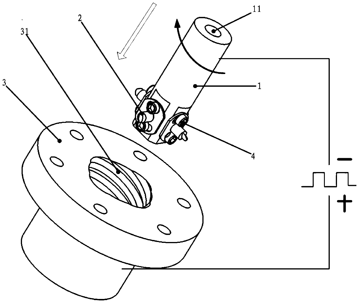
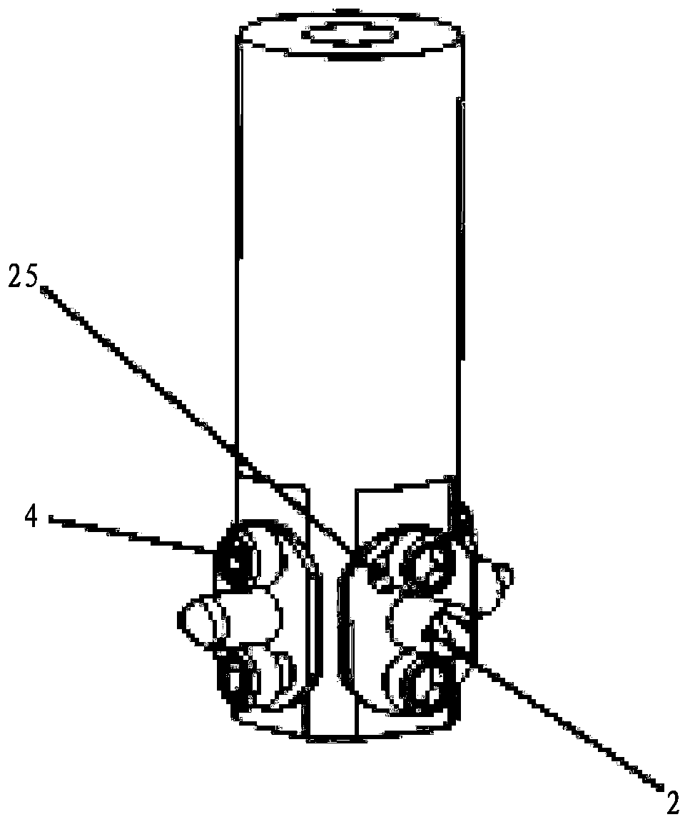
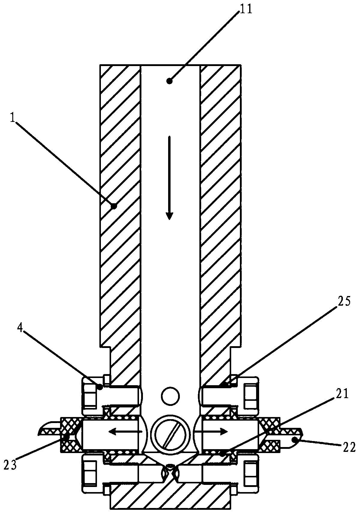
[0030] refer to Figure 1 to Figure 4 , the present embodiment relates to a processing device for processing large-lead nuts, including a hollow clamping rod 1, a cathode piece 2 and a nut 3, and the cathode piece 2 is installed on the outer circumference of the lower end of the hollow clamping rod 1; the hollow clamping The axis of the holding rod 1 coincides with the axis of the nut 3, and the normal direction of the cathode piece 2 is the same as the tangential direction of the spiral raceway 31 of the nut 3; the hollow clamping rod 1 is provided with a slot 11 for an external electrolyte , and the lower end of the hollow clamping rod 1 is provided with a liquid spray port 23 communicating with the slot 11, and the electrolyte is directly sprayed to the cathode from the liquid spray port in a direction parallel to the outer surface of the cathode sheet 2 and along the outer surface of the cathode sheet 2. In the processing area between the sheet 2 and the nut 3; the hollow ...


PUM


Abstract

The invention discloses a machining device for a sheet cathode electrolyte direct injection machining a large-lead nut. The machining device comprises a hollow clamping rod, a cathode sheet and the nut; the cathode sheet is installed on the outer circumference of the lower end of the hollow clamping rod; the axis of the hollow clamping rod coincides with the axis of the nut, and the normal direction of the cathode sheet is the same as the tangent direction of a spiral rolling path of the nut; and a liquid spraying outlet communicating with a groove hole is formed in the lower end of the hollowclamping rod, and the electrolyte is directly injected from the liquid spraying outlet into a processing area between the cathode sheet and the nut in the direction parallel to the outer surface of the cathode sheet and along the outer surface of the cathode sheet. The invention further discloses a machining method. According to the machining device for the sheet cathode electrolyte direct injection machining the large-lead nut, the electrolyte is directly injected from the liquid spraying outlet of the hollow clamping rod into the processing area between the cathode sheet and the nut in thedirection parallel to the outer surface of the cathode sheet and along the outer surface of the cathode sheet, the movement journey of the electrolyte is greatly shortened, the loss of kinetic energyis reduced, the electrolyte products in the processing area can be better washed out and taken away, and the work efficiency is improved.

Description

technical field [0001] The invention relates to a processing device for processing large-lead nuts and a processing method thereof, in particular to a processing device and a processing method for processing large-lead nuts by direct injection of sheet catholyte. Background technique [0002] Large-lead ball screw nut pairs are widely used in automation equipment requiring high moving speed due to their high motion precision, small friction, stability, and low noise. Among them, the inner raceway of the large-lead nut is usually processed by mechanical grinding, but due to the interference problem, the helix angle can only reach 17° at most, and the helix angle can only be processed by special technology and complex equipment. to 35°. Germany proposed a hard turning process, which uses the envelope surface of the tool tip motion track to form a raceway, but the structure of this device is complex, the processing efficiency is low, and the requirements for the tool are high,...

Claims


Application Information

Patent Timeline
IPC IPC(8): B23H9/00B23H3/00B23H11/00
Inventor 张永俊张传运罗红平陈晓磊刘桂贤张琮源
Owner GUANGDONG UNIV OF TECH
Why Eureka
Eureka Blog
Learn More