single phase motor

A single-phase motor and rotor technology, applied to synchronous motors with stationary armatures and rotating magnets, magnetic circuit shape/style/structure, magnetic circuit stationary parts, etc. Efficiency reduction and other problems, to achieve the effect of reducing torque ripple, improving output, and ensuring startability

Inactive Publication Date: 2021-03-30
MABUCHI MOTOR
View PDF7 Cites 0 Cited by
  • Summary
  • Abstract
  • Description
  • Claims
  • Application Information

AI Technical Summary

Problems solved by technology

[0008] On the other hand, if the tooth angle is reduced, contrary to the above, although the reduction in motor output during high-speed rotation is improved, the efficiency of the motor is reduced because the interlinkage flux with the permanent magnet rotor is reduced. In addition, the following occurs: Problem: Increased torque ripple that becomes a vibration factor of the motor during driving (power-on)

Method used


Image

  • single phase motor
  • single phase motor
  • single phase motor

Examples


Embodiment Construction

[0035] Hereinafter, a single-phase motor as an embodiment will be described with reference to the drawings. The embodiments shown below are merely examples, and it is not meant to exclude the application of various modifications and techniques not explicitly described in the following embodiments. Each structure of this embodiment can be implemented with various modifications within the range which does not deviate from the gist. In addition, they can be selected according to need, or can be combined appropriately.

[0036] (structure)

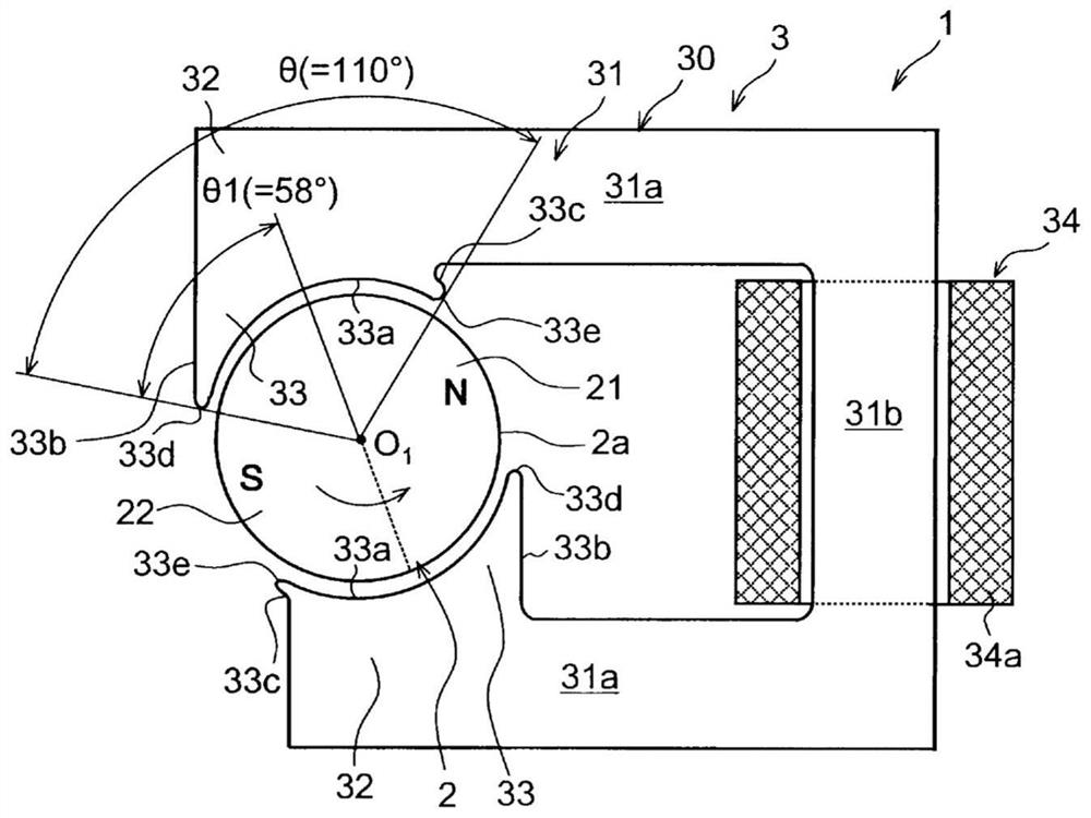
[0037] Such as figure 1 As shown, this single-phase motor (hereinafter simply referred to as a motor) 1 is an inner-rotor type two-pole two-slot single-phase brushless motor having a rotor 2 arranged inside and a stator 3 arranged outside.

[0038] The rotor 2 has permanent magnets, and N poles 21 and S poles 22 are arranged on the outer periphery of the rotor 2 with a phase shift of 180 degrees. The rotor 2 revolves around the center of r...


PUM


Abstract

To provide a single-phase motor capable of preventing generation of such a situation that a torque becomes zero at driving and thereby securing an initiation property while improving an output of a motor at high-speed rotation and suppressing torque ripples.SOLUTION: A single-phase motor comprises: a rotor 1 that has a permanent magnet; and a stator 3 that consists of a stator core 30 arranged at an outer periphery of the rotor 1 via an air gap from the rotor 1 and having a pair of tooth parts 33 opposed to the rotor 1, and a coil 34 equipped around the tooth parts. A tooth angle, which is a mechanical angle of an angle region facing the rotor outer periphery at front ends of the tooth parts 33, is equal to or more than 40° and equal to or less than 120°. An angle ratio R(=θ1 / θ) of a progressing side angle θ1, which is obtained by dividing the angle region into two at a reference position by using a circumferential position of the tooth parts that is set from a rotor phase at the time when a reverse induction voltage becomes zero as a reference position, and the tooth angle θ, is equal to or more than 0.51.SELECTED DRAWING: Figure 1

Description

technical field [0001] The present invention relates to a single-phase motor using a permanent magnet rotor. Background technique [0002] In a single-phase motor using a permanent magnet rotor, a pair of tooth portions are arranged to face each other across the rotor. Such a single-phase motor can be easily configured including a drive circuit and is relatively inexpensive, but there is a problem in starting performance in principle. Therefore, techniques for improving startability have been developed. For example, Patent Document 1 or the like discloses techniques for improving startability by eccentricizing the surface of the teeth facing the rotor or by providing recesses in the teeth. [0003] prior art literature [0004] patent documents [0005] Patent Document 1: Japanese Patent No. 3462043 Contents of the invention [0006] The problem to be solved by the invention [0007] However, in the above-mentioned single-phase motor, if the angle of the tooth portio...

Claims


Application Information

Patent Timeline
Patent Type & Authority Patents(China)
IPC IPC(8): H02K21/14H02K1/12
Inventor 日下部涉
Owner MABUCHI MOTOR
Why Eureka
Try Eureka