
Floor tile laying structure

A pavement and brick technology, which is applied in the direction of building structure, floor, building, etc., can solve the problems of stress superposition and concentration, arching and falling off, plate hollowing, etc., to suppress expansion and contraction stress, prevent plate hollowing, The effect of increasing the service life

Inactive Publication Date: 2019-06-11
王世强
View PDF0 Cites 1 Cited by
  • Summary
  • Abstract
  • Description
  • Claims
  • Application Information

AI Technical Summary

Problems solved by technology

During the construction of large-area dense joints of such large-scale slabs, stress superposition and concentration may occur, resulting in hollowing, arching, falling off or cracking of the slab.

Method used


Image

  • Floor tile laying structure
  • Floor tile laying structure
  • Floor tile laying structure

Examples


Embodiment Construction

[0020] The specific embodiments of the present invention will be described in further detail below in conjunction with the drawings and embodiments. The following examples are used to illustrate the present invention, but not to limit the scope of the present invention.

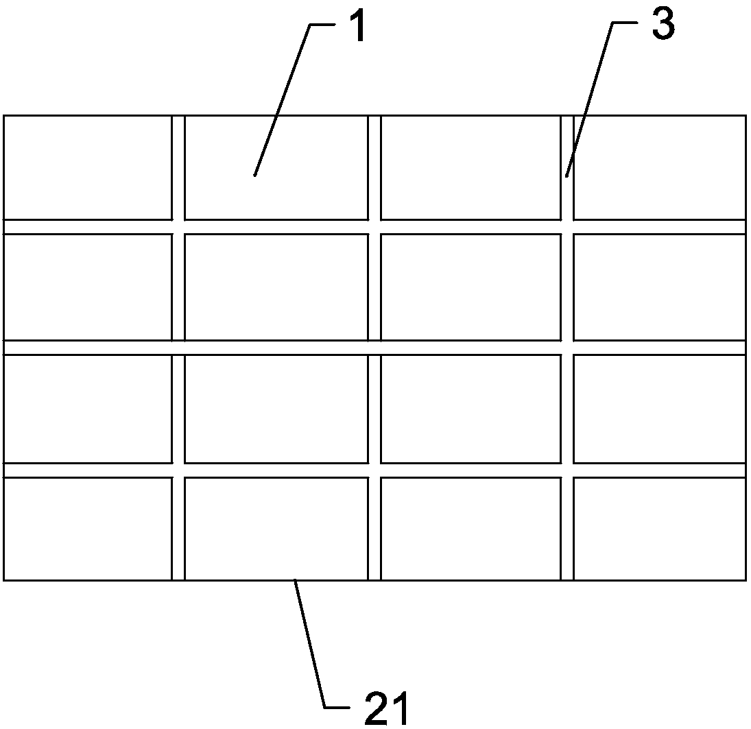
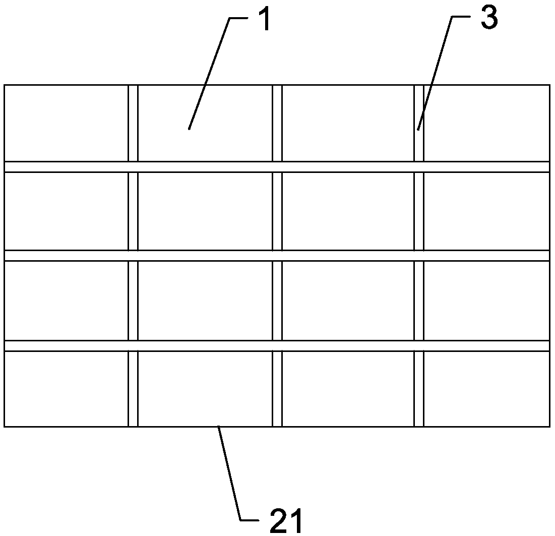
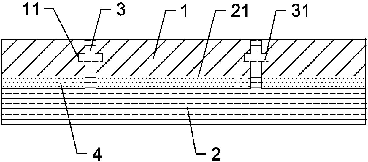
[0021] Such as figure 1 with figure 2 As shown, a slab paving structure includes a slab 1 and a paving mat 2. The paving mat 2 is provided with a grid 21 separated by a partition 3 and adapted to accommodate the slab 1. A convex rib 31 is provided on the side wall of the plate 3, and a groove 11 is provided on the side wall of the plate brick 1 corresponding to the convex rib 31 with a groove 11 that engages with the convex rib 31. Further, a buffer layer 4 is provided between the slab 1 and the paving mat 2. The paving mat 2 and the partition 3 are made of wood, alloy, plastic, rubber, composite board or plastic steel profile.

[0022] The slab-brick paving structure of this technical scheme discards the tradi...


PUM


Abstract

The invention provides a floor tile laying structure, which comprises floor tiles and a laying cushion. Lattice grooves which are partitioned by partition plates and accommodate the floor tiles in a matched mode are formed in the laying cushion, convex edges are arranged on the side walls of the partition plates, and grooves clamped with the convex edges in a matched mode are formed in the positions, corresponding to the convex edges, of the side walls of the floor tile. The floor tile laying structure is simple in structure and good in overall laying effect, capable of restraining expansion and contraction stress, convenient to construct and high in laying and demounting efficiency.

Description

Technical field [0001] The present invention relates to a composite floor tile installation structure in building materials, especially on the ground, terrace or wall of a building as a floor mat of building materials, and in particular to a tile paving structure. Background technique [0002] The paving method of floor tiles: stone and ceramics generally need to be bonded with cement, solid wood and plastic wood need to be made on the floor, and ordinary permeable bricks and silica sand permeable bricks need to be bonded with leveling layers. This traditional paving method is troublesome in construction and low in paving efficiency. It also brings a lot of trouble to the constructor due to the complexity of the paving, and it wastes a lot of manpower because of the problems of moving multiple materials. [0003] When paving slabs and tiles, in order to make the door entrance, roof, balcony, terrace and other floors have the buffer and anti-skid function, they can only choose the m...

Claims


Application Information

Patent Timeline
Patent Type & Authority Applications(China)
IPC IPC(8): E04F15/02
Inventor 王世强
Owner 王世强
Learn More