
Cleaning device for oil smoke purification equipment

A technology of oil fume purification and cleaning device, which is applied in the direction of using liquid cleaning method, electrode cleaning, cleaning method and utensils, etc., which can solve the problems of reducing the working efficiency of oil fume purification equipment, unable to clean oil dirt in corners, poor cleaning effect, etc., and achieve increase Practicality, improvement of environmental protection efficiency, and the effect of easy washing

Pending Publication Date: 2019-06-11
REED XINXIANG ROAD INC
View PDF0 Cites 3 Cited by
  • Summary
  • Abstract
  • Description
  • Claims
  • Application Information

AI Technical Summary

Problems solved by technology

[0002] The oil fume purification equipment is an innovative technology that uses electrostatic adsorption to collect dust, so that the oil fume can be converted into clean air instantly. During the long-term use of the oil fume purification equipment, the internal filter element will accumulate a thick oil layer, and the oil layer will block the filter element , leading to the purification effect of the oil fume purification equipment and reducing the working efficiency of the oil fume purification equipment. Therefore, in order to ensure the purification effect of the oil fume purification equipment, it is necessary to regularly disassemble and wash the filter element of the oil fume purification equipment, and the existing oil fume purification equipment. Most of the filter elements are cleaned by flushing, which is a waste of water, which is not conducive to environmental protection and causes environmental pollution. At the same time, the cleaning effect of the existing oil fume purification equipment with cleaning devices is poor, and the grease in the corners cannot be cleaned.

Method used


Image

  • Cleaning device for oil smoke purification equipment
  • Cleaning device for oil smoke purification equipment
  • Cleaning device for oil smoke purification equipment

Examples


Embodiment Construction

[0016] The following will clearly and completely describe the technical solutions in the embodiments of the present invention with reference to the accompanying drawings in the embodiments of the present invention. Obviously, the described embodiments are only some, not all, embodiments of the present invention. Based on the embodiments of the present invention, all other embodiments obtained by persons of ordinary skill in the art without making creative efforts belong to the protection scope of the present invention.

[0017] In the description of the present invention, it should be noted that the terms "upper", "lower", "inner", "outer", "front end", "rear end", "both ends", "one end", "another end" The orientation or positional relationship indicated by etc. is based on the orientation or positional relationship shown in the drawings, and is only for the convenience of describing the present invention and simplifying the description, rather than indicating or implying that ...


PUM


Abstract

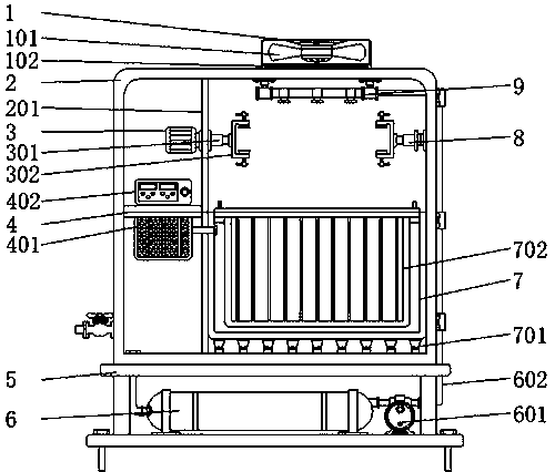
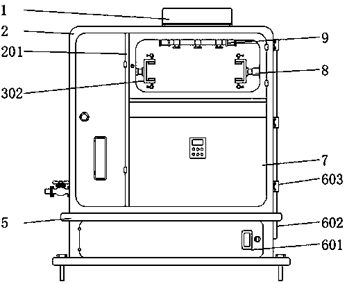
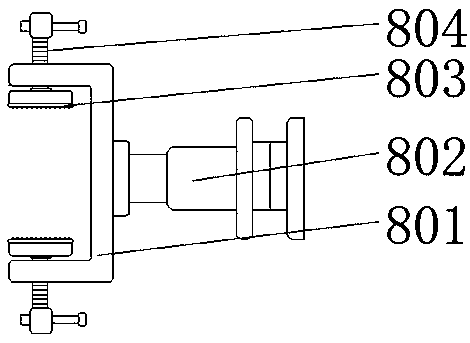
The invention discloses a cleaning device for oil smoke purification equipment. The cleaning device comprises a protection rack, a shell, a base, a filtering tank and a cleaning tank, wherein the shell is welded with the top of the base, a partition plate is welded with the shell, a motor is fixedly arranged at one side of the partition plate, the cleaning tank is arranged in the shell, a liquid storage box is connected with one side of the cleaning groove by a pipeline, a fixture is welded with one side of the shell, the filtering tank is welded with the bottom of the base, a water pump is connected with one side of the filtering tank by a hose, and an output end of the water pump is connected with a water spraying rack at an inner wall of the shell by a connection pipe. The filtering tank is arranged, a cleaning liquid can be repeatedly used, the waste of the cleaning liquid is prevented, the cost is reduced, and the environmental-friendly efficiency of the device is improved; and byarranging an ultrasound wave generator, the cleaning efficiency of the device can be improved, a filtering core can be rapidly cleaned, oil dirt in a corner of the filtering core can be cleaned, andthe cleaning effect of the filtering core is ensured.

Description

technical field [0001] The invention relates to the technical field of cleaning devices, in particular to a cleaning device for oil fume purification equipment. Background technique [0002] The oil fume purification equipment is an innovative technology that uses electrostatic adsorption to collect dust, so that the oil fume can be converted into clean air instantly. During the long-term use of the oil fume purification equipment, the internal filter element will accumulate a thick oil layer, and the oil layer will block the filter element , leading to the purification effect of the oil fume purification equipment and reducing the working efficiency of the oil fume purification equipment. Therefore, in order to ensure the purification effect of the oil fume purification equipment, it is necessary to regularly disassemble and wash the filter element of the oil fume purification equipment, and the existing oil fume purification equipment. Most of the filter elements are clean...

Claims


Application Information

Patent Timeline
Patent Type & Authority Applications(China)
IPC IPC(8): B03C3/74B03C3/78B08B3/12
Inventor 王九意赵金叶韩彪
Owner REED XINXIANG ROAD INC
Learn More