
Flywheel-type power supply device

A power supply device, flywheel technology, applied in the field of physics, can solve problems such as unsafe circuits, corrosion, maintenance troubles, etc.

Inactive Publication Date: 2019-06-07
上海龙程智能设备有限公司
View PDF0 Cites 2 Cited by
  • Summary
  • Abstract
  • Description
  • Claims
  • Application Information

AI Technical Summary

Problems solved by technology

And there are some problems in the use of the battery
For example, the maintenance is troublesome, the volume is large, it is not conducive to environmental protection, and there are certain unsafe factors (such as possible circuit corrosion, fire, explosion), etc.

Method used


Image

  • Flywheel-type power supply device

Examples


Embodiment 1

[0012] The flywheel power supply device of the present invention will be further described in detail below in conjunction with the accompanying drawings.

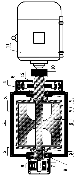
[0013] Such as figure 1 As shown, the flywheel power supply device of the present invention uses the flywheel to store energy and realize energy conversion. Mainly consists of equipment base 1, outer rotor 2, energy storage flywheel 3, coupling control generator stator 4, coupling control generator rotor 5, high-speed (energy supplement) motor stator 6, high-speed (energy supplement) motor rotor 7, flywheel shaft 8. Outer rotor transmission shaft 12 and bearing 9 are formed.

[0014] The flywheel 3 is connected with the high-speed (energy supplement) motor rotor 7 through the flywheel shaft 8, that is, the high-speed (energy supplement) motor rotor 7 is integrated with the flywheel 3 and the flywheel shaft 8. It is supported by bearings 9 at both ends and is placed inside the outer rotor 2 . The outer rotor 2 and the out...


PUM


Abstract

The invention discloses a flywheel-type power supply device. The flywheel-type power supply device comprises a base, an outer rotor transmission shaft, an outer rotor, a flywheel shaft, a flywheel, acontrol mechanism and an energy supplementing mechanism, wherein the base is of a hollow structure; the outer rotor transmission shaft is arranged at one end of the base in a penetrating mode; the outer rotor is arranged in the base, one end of the outer rotor is connected with the outer rotor transmission shaft, and the other end of the outer rotor is connected with the other end of the base; theflywheel shaft is arranged in the base, one end of the flywheel shaft is connected with the outer rotor transmission shaft, and the other end of the flywheel shaft is connected with the other end ofthe outer rotor; the flywheel is arranged on the flywheel shaft, and the flywheel is positioned in the outer rotor; the control mechanism is arranged at one end of the base and is connected with the outer rotor transmission shaft; and the energy supplementing mechanism is arranged at the other end of the base and is connected with the flywheel shaft. Compared with the prior art, the flywheel-typepower supply device has the following advantages that energy storage and release can be completed, and disadvantages caused by using a storage battery can be avoided.

Description

technical field [0001] The invention relates to the field of physics, in particular to an energy storage device, in particular to a flywheel power supply device. Background technique [0002] UPS power supply is generally used for storage and release of electric energy. In the prior art, a UPS power supply uses a battery as an energy storage element. And there are some problems in the battery in use. For example, the maintenance is troublesome, the volume is large, it is not conducive to environmental protection, and there are certain unsafe factors (such as possible circuit corrosion, fire, explosion) and so on. Contents of the invention [0003] In view of the above technical problems, the object of the present invention is to provide a flywheel power supply device that solves the above technical problems. [0004] In order to solve the above technical problems, the flywheel power supply device of the present invention includes: a base, the base is a hollow structure;...

Claims


Application Information

Patent Timeline
Patent Type & Authority Applications(China)
IPC IPC(8): H02K7/02
CPCY02E60/16
Inventor 郭清友朱宗兴计国平程惠中
Owner 上海龙程智能设备有限公司
Learn More