
Crushed aggregate separation device

A separation device and crushed material technology, applied in the direction of solid separation, recycling technology, wind shaker, etc., can solve the problems affecting the health of workers in the production environment of the workshop, increase labor costs, reduce recycling income, etc., to ensure the production environment. , reduce adhesion, the effect of uniform size

Pending Publication Date: 2019-06-07
广东新中南电缆有限公司
View PDF0 Cites 3 Cited by
  • Summary
  • Abstract
  • Description
  • Claims
  • Application Information

AI Technical Summary

Problems solved by technology

[0002] Cables that are burnt and damaged by high current and voltage flow or unusable due to negligence during production and processing will become waste cables. In order to recycle the copper in waste cables, it is necessary to break the waste cables into granules. Then use the separation and screening mechanism to separate copper particles and plastics, but in the prior art, the crushing and separation of materials are separated, and manual transportation of materials is required, which increases labor costs and reduces separation efficiency. During the process of transportation and separation, metal and plastic dust will be generated, which seriously affects the production environment of the workshop and the health of the staff; and the separation effect of the existing separation and screening mechanism is average. After the plastic is separated, copper particles are still mixed. Greatly reduces recycling gains

Method used


Image

  • Crushed aggregate separation device
  • Crushed aggregate separation device
  • Crushed aggregate separation device

Examples


Embodiment Construction

[0023] The present invention provides a crushing material separation device. In order to make the purpose, technical solution and effect of the present invention clearer and clearer, the present invention will be further described in detail below with reference to the accompanying drawings and examples. It should be understood that the specific embodiments described here are only used to explain the present invention, and are not intended to limit the protection scope of the present invention.

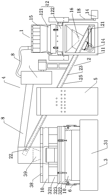
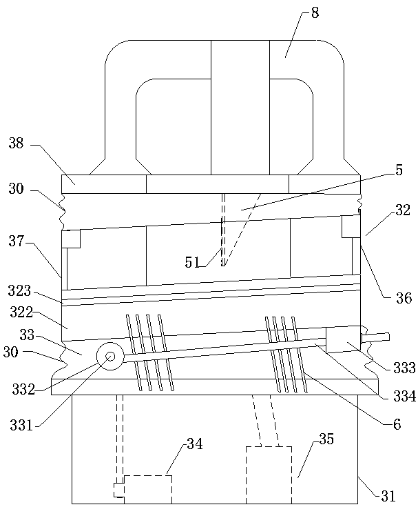
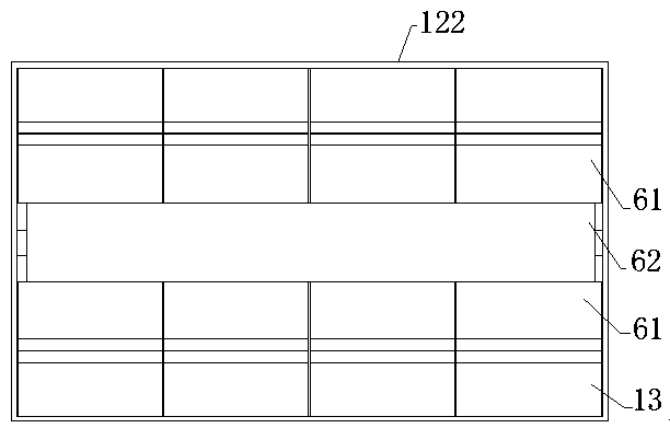
[0024] see Figure 1-Figure 5 , the present invention provides a crushing material separation device, including a crushing mechanism 1, a transport mechanism 2, a shaker separation mechanism 3, and a dust removal mechanism 4. The crushing mechanism 1 includes a bracket 11, a casing 12, and a fixed The cutter 13, the rotary cutter assembly and the first drive mechanism 14, the casing 12 is arranged on the support 11, and the first drive mechanism 14 is used to drive the rotary cutter as...


PUM


Abstract

The present invention discloses a crushed aggregate separation device. The crushed aggregate separation device comprises a crushing mechanism, a transportation mechanism, a shaking table separation mechanism and a dust removal mechanism. The crushing mechanism comprises a support, a case, a fixed cutting tool, a rotation cutting tool module and a first drive mechanism, material transportation between the crushing mechanism and the shaking table separation mechanism is achieved through the transportation mechanism, the shaking table separation mechanism comprises a pedestal, a shaking table arranged at the upper side of the pedestal, eccentric swing mechanisms, and a second drive mechanism and a blower mechanism which are arranged in the pedestal. Compared to the prior art, a discarded cable is cut to particle mixture through the crushing mechanism, particles in the particle mixture are more uniformly dispersed on the shaking table under the blowing of the blowing airflow to reduce bonding, then eccentric swing mechanisms are combined to perform further vibration separation for the shaking table to achieve automatic recycle of metal in the discarded cable so that the separation effect of the metal particulate matters and plastic particulate matters is good and the recycle profit is high.

Description

technical field [0001] The invention relates to the field of cable recycling, in particular to a scrap separation device. Background technique [0002] Cables that are burnt and damaged by high current and voltage flow or unusable due to negligence during production and processing will become waste cables. In order to recycle the copper in waste cables, it is necessary to break the waste cables into granules. Then use the separation and screening mechanism to separate copper particles and plastics, but in the prior art, the crushing and separation of materials are separated, and manual transportation of materials is required, which increases labor costs and reduces separation efficiency. During the process of transportation and separation, metal and plastic dust will be generated, which seriously affects the production environment of the workshop and the health of the staff; and the separation effect of the existing separation and screening mechanism is average. After the pl...

Claims


Application Information

Patent Timeline
IPC IPC(8): H01B15/00B03B4/02
CPCY02W30/82
Inventor 谭远燊叶芳荣朱冠潮罗伟波蒋三佑
Owner 广东新中南电缆有限公司
Learn More