
Transformer oil level temperature controller detection and identification method

A recognition method and transformer technology, applied in character and pattern recognition, instruments, computer parts, etc., can solve the problems of poor detection effect and lack of remote transmission function of intelligent instruments, so as to improve the efficiency of inspection and increase the number of indications. The effect of recognition accuracy and impact reduction

Active Publication Date: 2019-06-07
CRSC RESEARCH & DESIGN INSTITUTE GROUP CO LTD
View PDF12 Cites 1 Cited by
  • Summary
  • Abstract
  • Description
  • Claims
  • Application Information

AI Technical Summary

Problems solved by technology

Due to cost and historical reasons, most transformer oil level thermostats do not have the remote transmission function of smart meters, and only inspection robots can use computer vision to read the data indicated by the meter.
The premise of accurately identifying the indication of the transformer oil level thermostat is to accurately detect the position of the transformer oil level thermostat in the visual image, and most of the transformer oil level thermostats are outdoors. At present, most methods use traditional image The detection and identification are carried out by means of processing. In the case of changing lighting conditions, the detection effect is not good. Generally, a set of parameters is required for one lighting condition. In the identification process, there are also situations such as different outdoor lighting and different shooting angles of inspection robots.

Method used


Image

  • Transformer oil level temperature controller detection and identification method
  • Transformer oil level temperature controller detection and identification method
  • Transformer oil level temperature controller detection and identification method

Examples


Embodiment Construction

[0055]In order to make the purpose, technical solutions and advantages of the embodiments of the present invention more clear, the technical solutions in the embodiments of the present invention will be clearly and completely described below in conjunction with the accompanying drawings in the embodiments of the present invention. Obviously, the described embodiments It is a part of embodiments of the present invention, but not all embodiments. Based on the embodiments of the present invention, all other embodiments obtained by persons of ordinary skill in the art without making creative efforts belong to the protection scope of the present invention.

[0056] Such as figure 1 As shown, the embodiment of the present invention introduces a transformer oil level temperature controller detection and identification method, including the following steps:

[0057] Step 1: The inspection robot arrives at the designated location to obtain the picture of the oil level thermostat of th...


PUM


Abstract

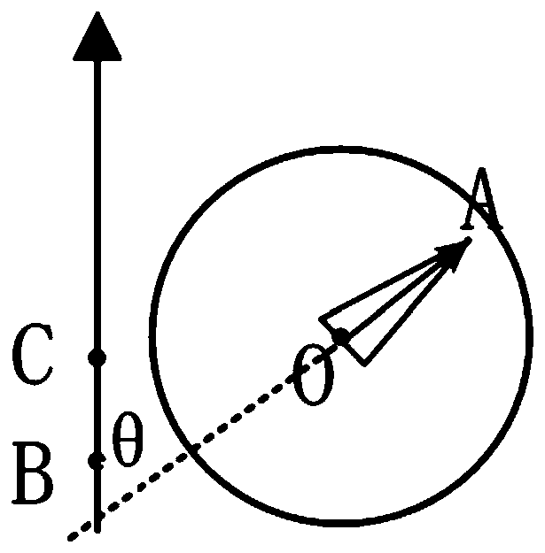
The invention discloses a transformer oil level temperature controller detection and identification method, and the method comprises the steps: enabling an inspection robot to reach a designated position, and obtaining a to-be-detected transformer oil level temperature controller image; secondly, screening a final target image of a target transformer oil level temperature controller area based onthe to-be-detected transformer oil level temperature controller picture; then, a target image is read in, and different image preprocessing operations are adopted according to the color of the pointer; secondly, positioning the instrument by using a target detector, dividing a dial plate area, and eliminating interference factors outside the dial plate of the transformer oil level temperature controller; then, extracting a pointer contour by using a corresponding method according to the pointer color; and finally, calculating the rotation direction and the pointing reading of the pointer by using a cosine law. By adopting the method, the transformer oil level temperature controller under various illumination and posture changes can be detected and identified.

Description

technical field [0001] The invention relates to the field of electric power inspection robots, in particular to a method for detecting and identifying a transformer oil level temperature controller. Background technique [0002] The power inspection robot needs to realize the basic functions such as autonomous positioning and navigation in the substation, field instrument display number recognition, and automatic charging. The core function is to detect and identify the indications of instruments and meters of on-site electrical equipment. [0003] At present, it is difficult for the power inspection robot to detect and identify the readings of the transformer oil level thermostat. Due to cost and historical reasons, most transformer oil level thermostats do not have the remote transmission function of smart meters, and inspection robots can only read the meter indications through computer vision. The premise of accurately identifying the indication of the transformer oil ...

Claims


Application Information

Patent Timeline
Patent Type & Authority Applications(China)
IPC IPC(8): G06K9/20G06K9/46G06K9/62
Inventor 廖婕陆子清韦佳贝王弈心姚书龙唐志勇朱兵陈成全潘卫国陈晖其他发明人请求不公开姓名
Owner CRSC RESEARCH & DESIGN INSTITUTE GROUP CO LTD
Learn More