
Aeroelastic model of suspended monorail wind tunnel test pier stud

An aeroelasticity and wind tunnel test technology, which is applied in the field of rail transit, can solve problems such as the inability to satisfy the similarity principle between the scaled model and the prototype structure, affect the accuracy of the test results of the aeroelastic model, and change the structural parameters of the model. The test is true, accurate and reliable, the effect is good, and the effect of setting is convenient

Pending Publication Date: 2019-06-07
CHINA CONSTR FIFTH ENG DIV CORP LTD
View PDF0 Cites 2 Cited by
  • Summary
  • Abstract
  • Description
  • Claims
  • Application Information

AI Technical Summary

Problems solved by technology

[0004] Traditional wind tunnel test bridge pier-column scaled-scale aeroelastic models are generally made in the form of a combination of core beams and jackets, that is, steel core beams are used inside the bridge pier scaled-down model to ensure the tensile stiffness, longitudinal bending stiffness, and The lateral bending stiffness and torsional stiffness are similar to the actual bridge pier structure. The exterior adopts ABS board to simulate the actual structure shape. Additional copper blocks or other high-density metal blocks are added to the hollow plate for counterweight to ensure that the quality of the model is similar to that of the prototype structure. In this way, the coat provides additional rigidity to the model structure to a certain extent, and at the same time increases The damping of the structure changes the parameters of the model structure, which cannot satisfy the principle of similar stiffness between the scale model and the prototype structure, which affects the accuracy of the results of the aeroelastic model test

Method used


Image

  • Aeroelastic model of suspended monorail wind tunnel test pier stud
  • Aeroelastic model of suspended monorail wind tunnel test pier stud
  • Aeroelastic model of suspended monorail wind tunnel test pier stud

Examples


Embodiment

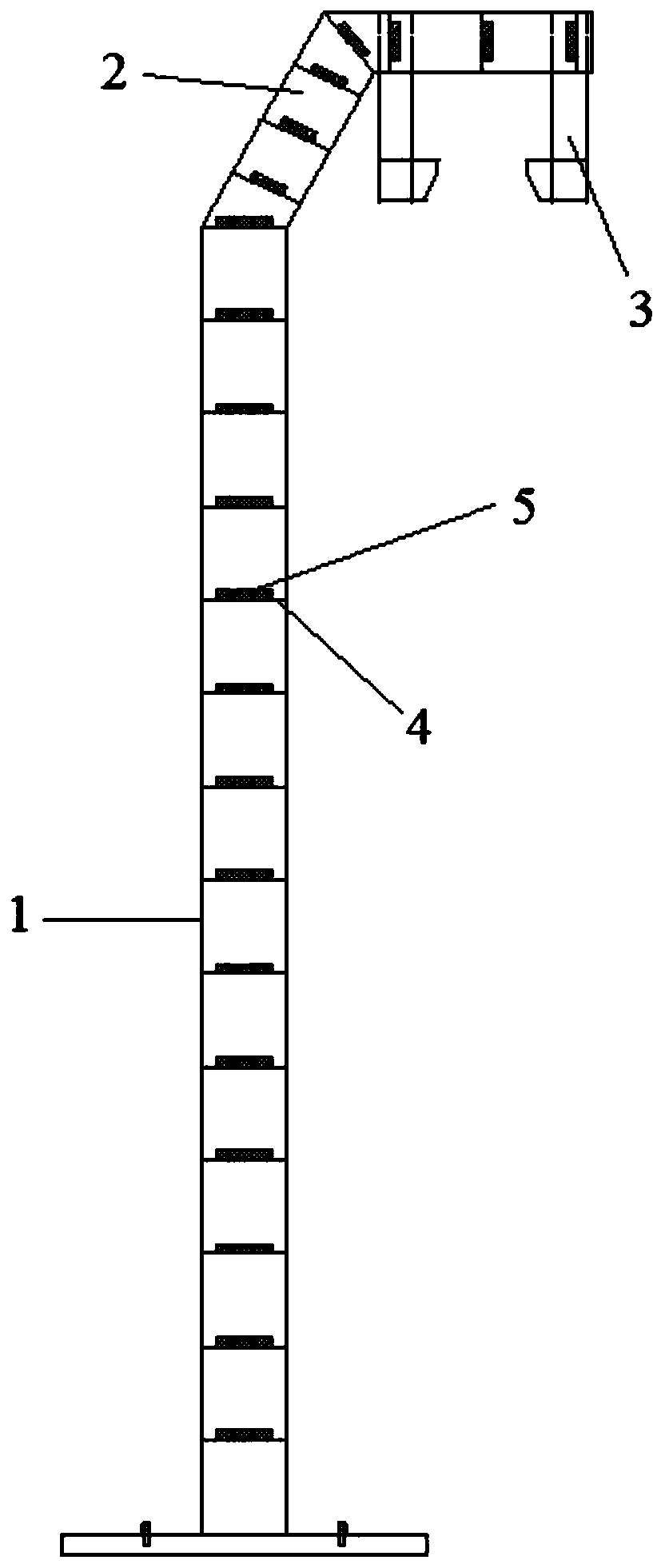
[0024] Such as Figure 1-3 As shown, the aeroelastic model of a suspended monorail wind tunnel test pier column according to the present invention includes a pier body 1 and a cantilever end 2 .

[0025] The cantilever end 2 is connected to the top of the pier body 1, and the cantilever end 2 is provided with a down-curved corbel 3. Both the pier body 1 and the cantilever end 2 are steel box structures, and the pier body 1 It includes four steel columns, the four steel columns are arranged in a rectangular shape, and steel plates are welded between two adjacent steel columns.

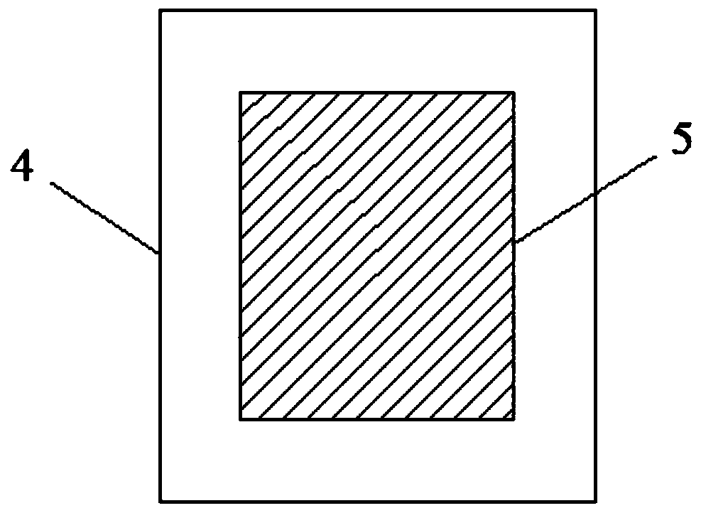
[0026] The pier body 1 and the cantilever end 2 are respectively provided with several steel partitions 4 at intervals along their respective length directions, and each steel partition 4 is welded to the corresponding pier body 1 or the cantilever end 2 Each of the steel partitions 4 is provided with a counterweight 5, and each of the counterweights 5 is bonded to the corresponding steel partition 4 b...


PUM


Abstract

The invention discloses an aeroelastic model of a suspended monorail wind tunnel test pier stud. The aeroelastic model comprises a pier body and a cantilever end. The cantilever end connected to the top of the pier body is provided with a lower bending bracket. The pier body and the cantilever end have steel box structures and each of the pier body and the cantilever end is provided with a plurality of steel partition plates at intervals in a respective length direction; each steel partition plate is connected with a counterweight block; and each counterweight block is not in contact with theinner wall of the pier body or the inner wall of the cantilever end. According to the aeroelastic model, the additional mass is provided by using all counterweight blocks to meet the model need; sincethe counterweight blocks are not in contact with the inner wall of the pier body or the inner wall of the cantilever end, the structural damping influence is avoided; the counterweight blocks are arranged discontinuously in the respective length direction of the pier body or the cantilever end to prevent the influence on the rigidity of the structure, so that conformity to the actual condition ofthe structure is improved and the wind tunnel test becomes real, accurate and reliable. The aeroelastic model has advantages of simple structure, great convenience in setting, and good effect.

Description

technical field [0001] The invention relates to the field of rail transportation, in particular to an aeroelastic model of a suspended monorail wind tunnel test pier column. Background technique [0002] Suspended monorail is a rail transit system in which vehicles are directly suspended below the track beam, also known as empty rail, which belongs to urban monorail traffic. The bridge span structure is mostly all-steel structure, which is composed of box-shaped track beams and pier columns. The vehicle tires are rubber tires. The load-bearing wheels are supported on the cantilever bottom plate under the track beam. Board, relying on motor drive to achieve vehicle operation. Suspended monorail transportation expands urban public transportation into the air and realizes three-dimensional development. Because of its good cost performance, small space ratio, and coordination with the surrounding environment, it has become an alternative solution for small and medium-sized citi...

Claims


Application Information

Patent Timeline
Patent Type & Authority Applications(China)
IPC IPC(8): G01M9/08
Inventor 周帅方聪李水生谭立新
Owner CHINA CONSTR FIFTH ENG DIV CORP LTD
Learn More