A deep well precise positioning gravel filling water stop device

A technology of precise positioning and water-stopping devices, which is applied in wellbore/well components, sealing/packing, earthwork drilling and mining, etc. It can solve the problems of easy falling off of the gravel layer, irregular hole wall, gravel filling height, and water-stopping position Inaccurate and other problems, to achieve the effect of shortening the path of gravel filling, preventing "bridging and reliable delivery"

Active Publication Date: 2020-11-27
山东省地质矿产勘查开发局第三水文地质工程地质大队 +1
View PDF5 Cites 0 Cited by
  • Summary
  • Abstract
  • Description
  • Claims
  • Application Information

AI Technical Summary

Problems solved by technology

[0002] In the process of gravel throwing and water stop in deep wells, due to the small gap between the drilling hole wall and the well pipe and the irregular hole wall, when gravel is filled from the outside of the well pipe, it is easy to cause the gravel to be trapped between the drilling hole wall and the well pipe. "Bridging" between the gaps and the gravel filling is not dense enough, resulting in inaccurate gravel filling height and water stop position, seriously affecting the quality of well completion
In the existing technology, the gravel-attached water pipe is usually used instead of the conventional well pipe to avoid the well pipe as a gravel-filling process. However, the gravel-attached water pipe is easy to fall off, and the compressive, shear and flexural strength is low. There are still great limitations in the use of deep wells

Method used


Image

  • A deep well precise positioning gravel filling water stop device
  • A deep well precise positioning gravel filling water stop device
  • A deep well precise positioning gravel filling water stop device

Examples


Embodiment Construction

[0022] The following will clearly and completely describe the technical solutions in the embodiments of the present invention with reference to the accompanying drawings in the embodiments of the present invention. Obviously, the described embodiments are only some, not all, embodiments of the present invention. Based on the embodiments of the present invention, all other embodiments obtained by persons of ordinary skill in the art without making creative efforts belong to the protection scope of the present invention.

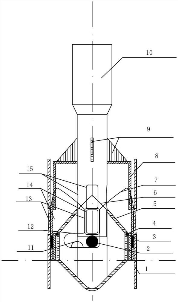
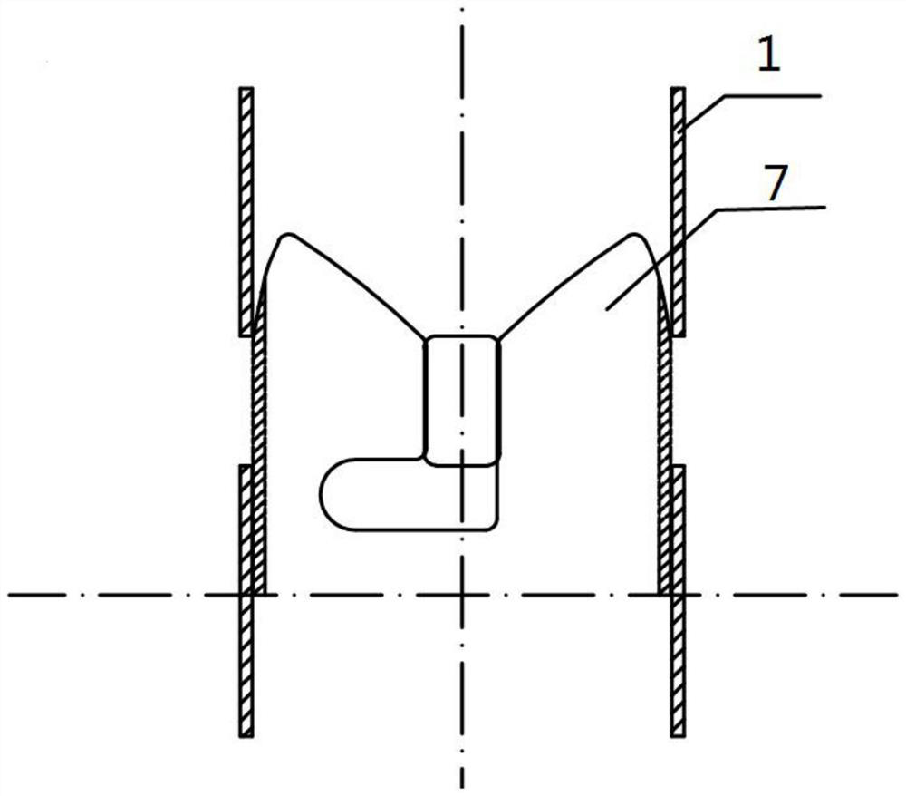
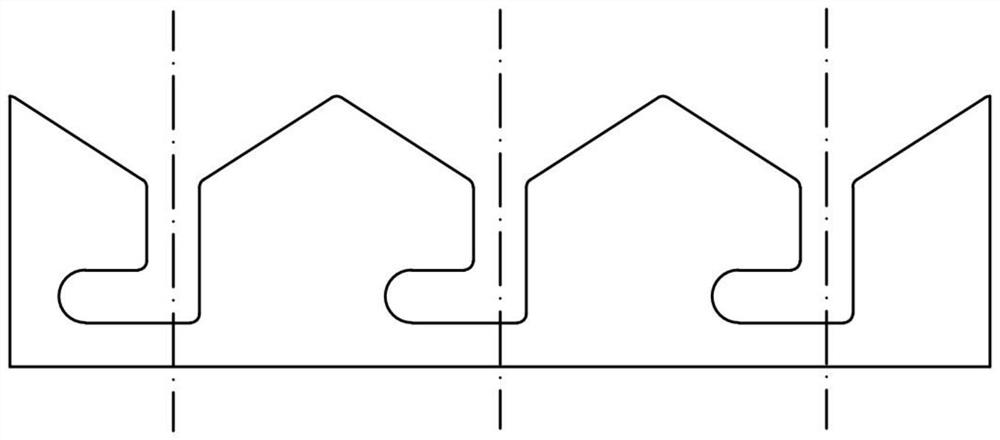
[0023] The purpose of the present invention is to provide a gravel-filling and water-stopping device with precise positioning for deep wells, so as to solve the problems existing in the prior art, and move the gravel-filling position from the wellhead to the underground, thereby shortening the gravel-filling path and delivering gravel reliably To the destination position, effectively prevent the occurrence of "bridging" phenomenon.

[0024] In order to make th...


PUM


Abstract

The invention discloses a precise positioning, gravel filling and water stop device for a deep well. The device includes positioning pipes and a gravel throwing device; the outside of the gravel throwing device is sleeved by the positioning pipes, and the positioning pipes are detachably connected with the positioning pipes; multiple first discharge openings are circumferentially and uniformly distributed on the pipe walls of the positioning pipes; the gravel throwing device includes a feeding drill rod, retention pipes and guide apparatuses; the guide apparatuses are fixedly connected with the upper part of the feeding drill rod; the feeding drill rod is movable connected with the retention pipes; the outer sides of the guide apparatuses are sleeved by the positioning pipes, and the outersides of the retention pipes are fixedly sleeved by the positioning pipes; multiple second discharge openings corresponding to the multiple first discharge openings are circumferentially and uniformly distributed on the pipe walls of the retention pipes; and multiple discharge openings are circumferentially and uniformly distributed on the pipe wall of the feeding drill rod. The device overcomesthe defects that gravel is prone to "bridge formation" between a wellbore wall and a well pipe in a conventional deep well gravel filling process, and gravel material filling is not dense enough, so that a gravel throwing position moves down to down-hole, thereby shortening a gravel filling path, and occurrence of a "bridge formation" phenomenon is effectively prevented.

Description

technical field [0001] The invention relates to the technical field of drilling gravel packing tools, in particular to a deep well precisely positioned gravel packing water stop device. Background technique [0002] In the process of gravel throwing and water stop in deep wells, due to the small gap between the drilling hole wall and the well pipe and the irregular hole wall, when gravel is filled from the outside of the well pipe, it is easy to cause the gravel to be trapped between the drilling hole wall and the well pipe. The gravel filling height and water stop position are not accurate, which seriously affects the quality of well completion. In the existing technology, the gravel-attached water pipe is usually used instead of the conventional well pipe to avoid the well pipe as a gravel-filling process. However, the gravel-attached water pipe is easy to fall off, and the compressive, shear and flexural strength is low. There are still great limitations in the use of de...

Claims


Application Information

Patent Timeline
Patent Type & Authority Patents(China)
IPC IPC(8): E21B33/12
Inventor 陈洪年战启帅余洋张强谭现锋王天放王进俊
Owner 山东省地质矿产勘查开发局第三水文地质工程地质大队
Why Eureka
Try Eureka