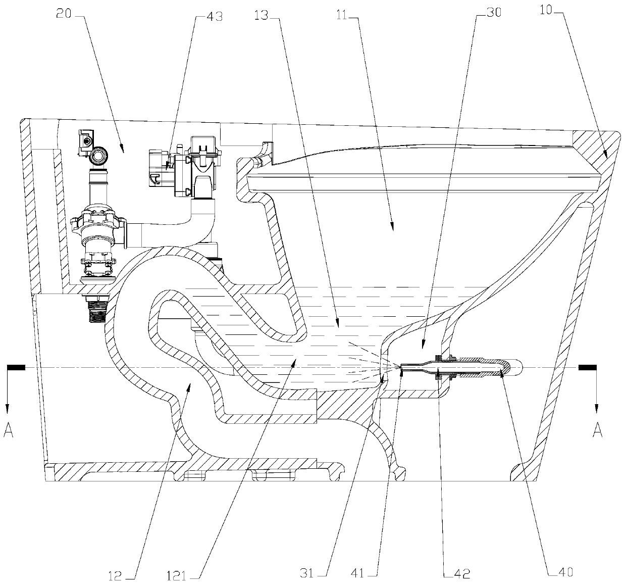
Closestool flushing control system

A control system and toilet technology, applied in flushing toilets, flushing equipment with water tanks, buildings, etc., can solve the problems of poor flushing effect, poor flushing effect, single flushing mode, etc., and achieve good flushing effect

Inactive Publication Date: 2019-06-07
厦门派夫特卫浴科技有限公司
View PDF6 Cites 2 Cited by
  • Summary
  • Abstract
  • Description
  • Claims
  • Application Information

AI Technical Summary

Problems solved by technology

[0004] With the traditional flushing mode, on the one hand, one waterway is used to flush the toilet water seal and the wall of the toilet bowl at the same time, often resulting in poor flushing effect due to insufficient flushing water flow; Waste of water in the case of waste, and insufficient or inconsistent flushing of the toilet in the case of a large amount of waste, the flushing effect is poor

Method used


Image

  • Closestool flushing control system
  • Closestool flushing control system
  • Closestool flushing control system

Examples


no. 1 example

[0106] like Figure 5 As shown, in this embodiment, the control sequences of the first flushing water circuit 30, the second flushing water circuit 40, and the brush ring water circuit 50 are as follows: first, the brush ring control device 51 is turned on, and the brush ring After the control device 51 is turned on for a first preset time, it is turned off; and after the brush ring control device 51 is turned off, the first control device 32 and the second control device 43 are turned on. The device 32 and the second control device 43 are turned on at the same time, or, after the brush ring control device 51 is turned off, the first control device 32 is turned on before or after the second control device 43 (0S~2S); Further, the water inlet device 21 for supplying water to the water tank 20 is also included. After the second control device 43 is turned off, the water inlet device 21 is turned on.

[0107] In this embodiment, the first preset time is 0.5S˜8S.

[0108] In thi...

no. 2 example

[0114] like Image 6 As shown, in this embodiment, the control sequences of the first flushing water circuit 30, the second flushing water circuit 40, and the brush ring water circuit 50 are as follows: first, the brush ring control device 51 is turned on, and the first preset After setting the time, the brush ring control device 51 is turned off; then, the first control device 32 , the second control device 43 and the water inlet device 21 are turned on.

[0115] In this embodiment, the first preset time is 0.5S˜8S.

[0116] It should be noted that, in this embodiment, when the first control device 32 and the second control device 43 are turned on at the same time, the water inlet device 21 is also turned on at the same time; when the first control device 32 is turned on When the time is earlier or later than the opening time of the second control device 43, preferably, earlier or later than the opening time of 0S~2S, the water inlet device 21, the first control device 32 an...

no. 3 example

[0120] like Figure 7 As shown, in this embodiment, the control sequence of the first flushing water circuit 30, the second flushing water circuit 40, and the brush ring water circuit 50 adopts: first, the brush ring control device 51 and the water inlet device are turned on at the same time. 21. The brush ring control device 51 is turned on for a second preset time and then turned off, and after the brush ring control device 51 is turned off, the first control device 32 and the second control device 43 are turned on.

[0121] In this embodiment, the second preset time is 0.5S˜8S.

[0122] The remaining undescribed parts of this embodiment are similar to those of the first embodiment, and will not be repeated here.


PUM


Abstract

The invention discloses a closestool flushing control system which comprises a first flushing water path, a second flushing water path and a brush ring water path, wherein the first flushing water path is communicated with a water tank and used for supplying flushing water to a water seal area, and a corresponding first control device is arranged; the second flushing water path is used for supplying pressure water to the water seal area, and a corresponding second control device is arranged; the brush ring water path is used for washing the basin part, and a corresponding brush ring control device is arranged; the brush ring control device is started before the first control device; or the brush ring control device and the first control device are started at the same time; or the first control device is started before the brush ring control device, water potential energy and waterkinetic energy are used simultaneously to flush the closestool, the flushing effect is better, multiple water paths of the first flushing water path, the second flushing water path and the brush ring water path are used and mutually matched, more diversified flushing modes are provided, and the water resource can be effectively saved on the basis that the flushing effect is guaranteed.

Description

technical field [0001] The invention relates to the technical field of toilets, in particular to a toilet flushing control system. Background technique [0002] The existing toilets are divided into a structure with a water tank and a structure without a water tank. The toilets with a water tank structure generally use the potential energy of the water in the water tank to flush the dirt in the toilet bowl, and the toilets without a water tank structure generally use the kinetic energy of tap water directly. Flush the toilet. [0003] During a flush cycle of a toilet, three purposes are usually met: the first is to remove dirt from the toilet bowl into the drain; the second is to clean the bowl wall to remove deposits or adherence to the bowl wall surface any solid or liquid dirt on the toilet; the third is a supplemental water seal, which leaves relatively clean water in the toilet between uses, and which forms a sufficient water seal to prevent sewer odors from entering ...

Claims


Application Information

Patent Timeline
Patent Type & Authority Applications(China)
IPC IPC(8): E03D11/02E03D5/10E03D9/00
CPCY02A20/40
Inventor 张凤荣黄贵阳钟志军
Owner 厦门派夫特卫浴科技有限公司
Why Eureka
Try Eureka