
Expansion shell bearing plate and anchor rod adopting same

A pressure-bearing plate and shell expansion technology, which is applied in the direction of sheet pile walls, buildings, and foundation structure engineering, can solve the problem of enhancing the bond strength between the anchor bolt grouting body and the rock-soil interface, and increasing the grouting body and the rock-soil body interface. Interface normal stress and other issues

Pending Publication Date: 2019-06-07
HUAQIAO UNIVERSITY
View PDF0 Cites 0 Cited by
  • Summary
  • Abstract
  • Description
  • Claims
  • Application Information

AI Technical Summary

Problems solved by technology

[0005] The purpose of the present invention is to provide an expanding shell bearing plate, so as to solve the problem that the existing plane bearing plate is difficult to enhance the bonding strength of the interface between the anchor grouting body and the rock-soil body, and can split the anchor after the prestress is applied. The grouting body causes radial expansion of the grouting body, which greatly increases the normal stress at the interface between the grouting body and the rock-soil body, thereby significantly improving the bonding strength of the interface and greatly increasing the pull-out bearing capacity of the bolt

Method used


Image

  • Expansion shell bearing plate and anchor rod adopting same
  • Expansion shell bearing plate and anchor rod adopting same
  • Expansion shell bearing plate and anchor rod adopting same

Examples


Embodiment 1

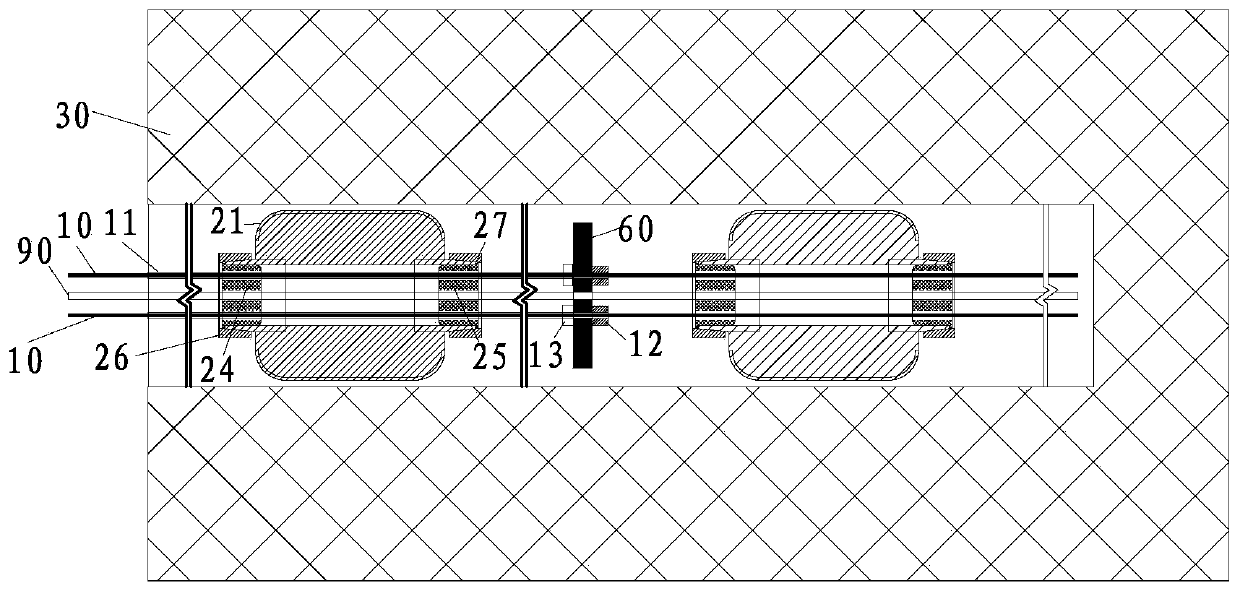
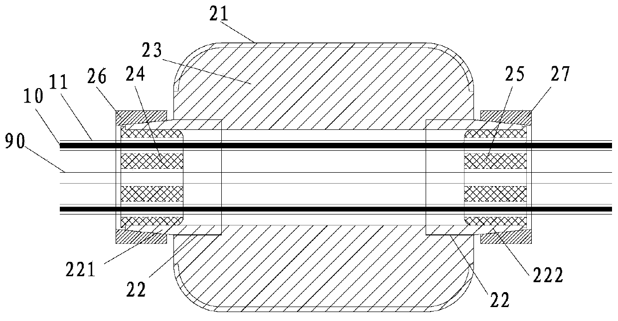
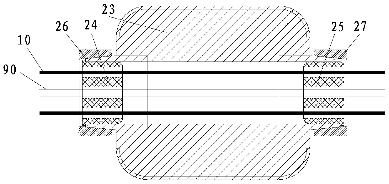
[0020] refer to Figure 1 to Figure 12, the present invention proposes a universal centering bracket, including a boat-shaped bracket, a first universal plug 24 , a second universal plug 25 , a first locking ring 26 and a second locking ring 27 . The boat-shaped support includes an outer cylinder 21, an inner cylinder 22 coaxially arranged at both ends of the outer cylinder 21, and a rib 23 connected between the outer cylinder 21 and the inner cylinder 22. The two ends of the inner cylinder 22 along the axial direction are provided with a first locking tongue cone. From the free end of the cylinder part 211 and the second cone cylinder part 212 toward the center of the inner cylinder 22, the outer diameters of the first cone cylinder part 211 and the second cone cylinder part 212 gradually increase. Large, the first universal plug 24 is embedded in the first deadbolt cone part 211, the second universal plug 25 is embedded in the second deadbolt cone part 212, the outer wall of...

Embodiment 2

[0027] refer to Figure 13 to Figure 23 , the assembled centering bracket, including a boat-shaped bracket and an assembly plug 40, the boat-shaped bracket includes an outer cylinder 21, an inner cylinder 22 coaxially arranged in the outer cylinder 21, and a rib 23 connected between the outer cylinder 21 and the inner cylinder 22, the inner The inner wall of the cylinder 22 is provided with an internal thread portion 225, and the outer wall of the assembly plug 40 is provided with an external thread portion 43 that cooperates with the internal thread portion 225. The assembly plug 40 is screwed into the inner cylinder 22, and the assembly plug 40 is provided with The reinforcement hole 41 for the anchor rod body 10 to pass through and the grouting pipe perforation 42 for pouring grout are respectively provided at both axial ends of the assembly plug 40 for restricting the movement of the assembly plug 40 on the anchor rod body 10 The first limiting member 51 and the second lim...

Embodiment 3

[0036] refer to Figures 24 to 27 , the present invention also proposes an expanding shell pressure bearing plate, which includes a conical pressure bearing plate, and the center of the conical pressure bearing plate is provided with a through hole 611 along the axial direction for the bolt body 10 to pass through, and the conical pressure bearing plate The plate has a flat plate portion 61 and a tapered portion 62 formed on the flat plate portion 61. The flat plate portion 61 and the tapered portion 62 are integrally formed. The two ends of the tapered portion 62 along the axial direction are respectively set as a connecting end and a free end. The diameter is larger than the outer diameter of the free end, and the connection between the connecting end and the flat plate portion 61 forms an annular extrusion platform 63, and the annular extrusion platform 63 is provided with a first annular pressure relief pad 64. As a preferred mode of the present invention, a second annular...


PUM

PropertyMeasurementUnit
Thicknessaaaaaaaaaa
Lengthaaaaaaaaaa
Wall thicknessaaaaaaaaaa

Abstract

The invention relates to an expansion shell bearing plate. The expansion shell bearing plate comprises a tapered bearing plate, a through hole allowing a rod body of an anchor rod is formed in the center of the tapered bearing plate in the axial direction, the tapered bearing plate is provided with a flat plate part and a tapered part, a connecting end and a free end are arranged at the two ends of the tapered part in the axial direction, the outer diameter of the connecting end is larger than that of the free end, an annular extrusion table is formed at the joint of the connecting end and theflat plate part, and the annular extrusion table is provided with a first annular yielding pad. According to the anchor rod, when prestress is applied, due to the fact that the first annular yieldingpad is arranged on the annular extrusion table, a second annular yielding pad is fixed to the end face of the free end, and the tapered bearing plate can release certain deformation when extruding agrouting material, that is, certain 'yielding' deformation is produced. In the process of 'yielding', the tapered surface of the tapered part can extrude the surrounding grouting material in the radial direction, thus the grouting material produces radial expansion, then extrudes surrounding rock and earth mass, consequently normal stress of the interface between the grouting material and the rockand earth mass is greatly increased, the bonding strength of the interface between the grouting material and the rock and earth mass can be significantly enhanced, and thus the uplift bearing capacity of the anchor rod is greatly improved.

Description

technical field [0001] The invention relates to an expanding shell pressure-bearing plate and a bolt using the expanding shell pressure-bearing plate, which can be used in projects such as mine roadway, traffic tunnel, water conservancy culvert support, foundation support and the like. Background technique [0002] In the bolt support system, for pressure bolts, pressure dispersion bolts, and tension-compression composite bolts, the pressure bearing plate is an important part of this type of bolt system. The anchor rod transmits the external load to the bearing plate through the unbonded rod body, squeezes the grouting body through the bearing plate, and then transfers the external load to the rock and soil mass through the bonding effect between the grouting body and the rock-soil mass interface. Therefore, the bonding strength between the grouting body and the rock-soil interface is extremely important to the pullout bearing capacity of the bolt. [0003] At present, the ...

Claims


Application Information

Patent Timeline
IPC IPC(8): E02D5/74
Inventor 涂兵雄王海涛俞缙贾金青张丽华蔡燕燕
Owner HUAQIAO UNIVERSITY
Learn More