
An automatic scribing device

An automatic scribing and driving shaft technology, applied in the field of machinery, can solve the problems that the device cannot withstand the impact force, beating, judge the reliability of the roller, etc., and achieve the effect of stable and reliable scribing, good conveying, and solving the effect of external splashing.

Active Publication Date: 2022-04-22
SHENYANG JIANZHU UNIVERSITY +1
View PDF7 Cites 0 Cited by
  • Summary
  • Abstract
  • Description
  • Claims
  • Application Information

AI Technical Summary

Problems solved by technology

However, when these devices work, other parts except the rollers are in a static state. These devices cannot bear the impact force, and the surface of the object to be marked is required to be flat and the speed of movement is constant when marking, otherwise the marking device will not be able to Running or jumping so that the line cannot be drawn normally
In addition, most of the ink bottles of the existing scribing devices are not provided with ink bottle caps, which cannot prevent the air pressure in the ink bottle from being affected by the outside world, cannot effectively control the flow of ink, and the ink is easy to splash during the work process, etc. In addition, the color of the line drawn by the scribing device on the market is single, and the marks left on the workpiece cannot intuitively judge the reliability of the contact between the roller and the workpiece.

Method used


Image

  • An automatic scribing device
  • An automatic scribing device

Examples


Embodiment Construction

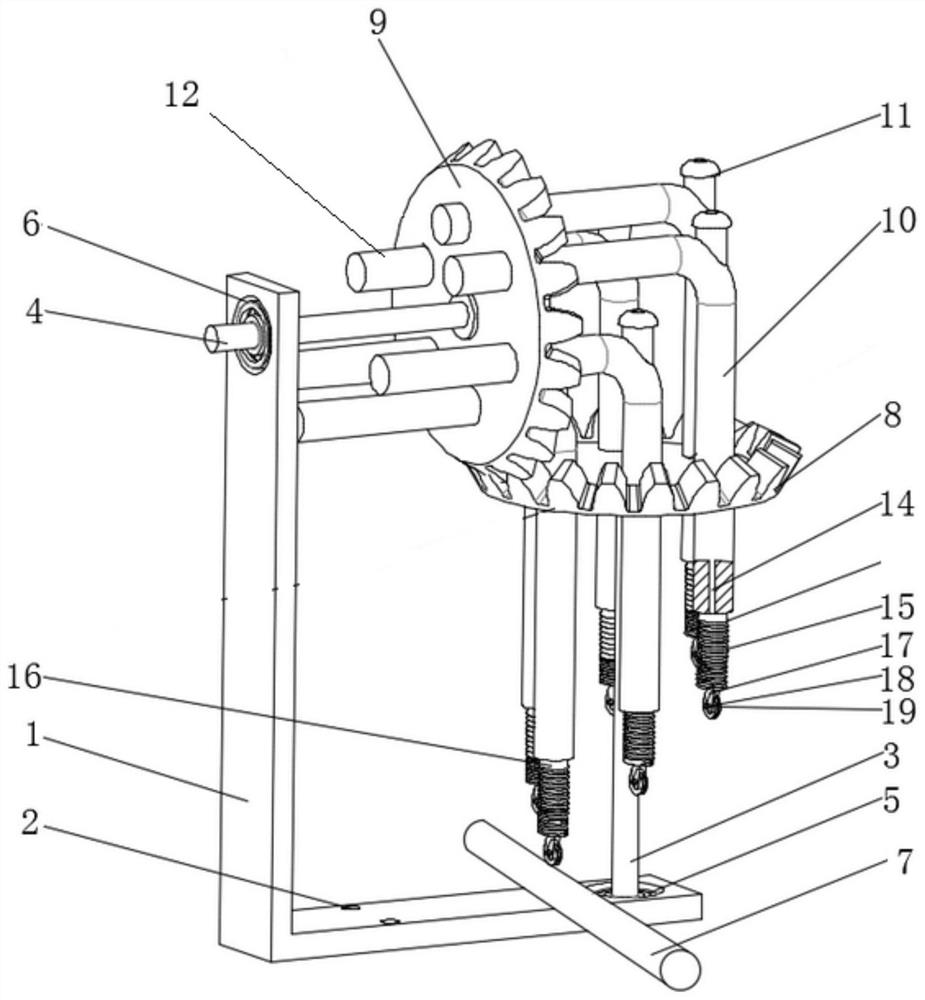
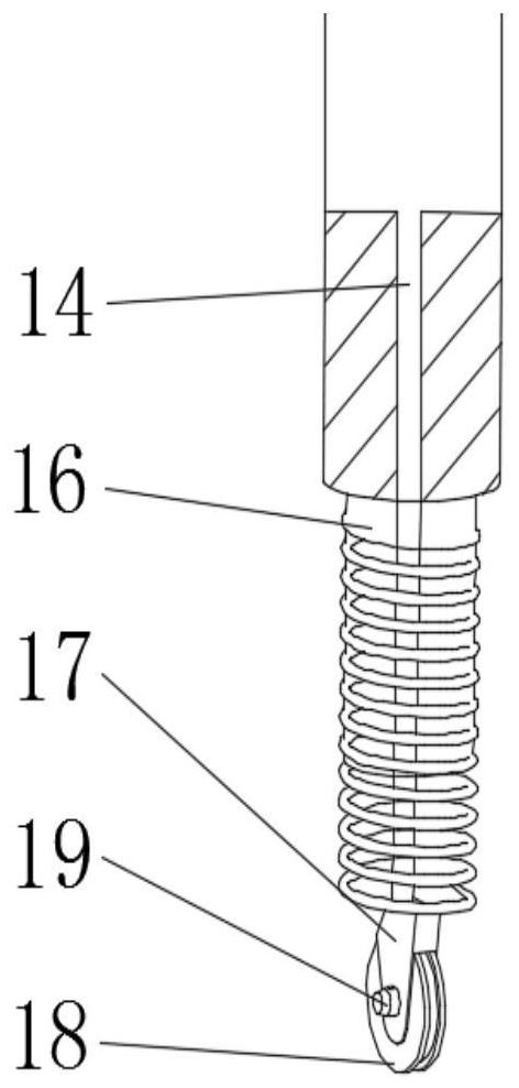
[0018] Such as figure 1 , 2 As shown, an automatic scribing device includes a bracket, a positioning and orientation matching mechanism and an ink outlet mechanism. The bracket includes a vertical plate 1 and a bottom plate 2 that are perpendicular to each other; 4. Bevel gear one 8 and bevel gear two 9, one end of the drive shaft 3 is installed on the base plate 2 through the bearing one 5, and the other end of the drive shaft 3 is fixedly installed at the center of the bevel gear one 8, so One end of the driven shaft 4 is installed on the vertical plate 1 through the bearing 2 6, and the other end of the driven shaft 3 is fixedly installed in the center of the bevel gear 2 9, and the bevel gear 1 8 meshes with the bevel gear 2 9, Bevel gear one 8 and bevel gear two 9 are respectively provided with six mounting holes uniformly distributed along the circumference; the ink outlet mechanism includes an ink bottle 10, an ink outlet head and a positioning rod 12, and the position...


PUM


Abstract

The invention belongs to the field of machinery, and in particular relates to an automatic scribing device. The technical scheme is as follows: it includes a bracket, a positioning and orientation matching mechanism and an ink outlet mechanism, the bracket includes a vertical plate and a bottom plate that are perpendicular to each other; the positioning and orientation matching mechanism includes a driving shaft, a driven shaft, a bevel gear 1 and a bevel gear 2, One end of the driving shaft is installed on the bottom plate through the first bearing, the other end of the driving shaft is fixedly installed in the center of the bevel gear 1, and one end of the driven shaft is installed on the vertical plate through the second bearing, The other end of the driven shaft is fixedly mounted on the center of the second bevel gear, the first bevel gear meshes with the second bevel gear, and the first bevel gear and the second bevel gear are provided with a plurality of mounting holes evenly distributed along the circumference; the ink outlet The mechanism includes an ink bottle, an ink outlet and a positioning rod, the positioning rod is vertically installed at the top of the ink bottle, the ink outlet is installed at the bottom end of the ink bottle; the ink bottle is installed on a bevel gear. The positioning rod is installed in the installation hole of the second bevel gear. The invention has simple structure, stable and reliable operation, and is suitable for scribing work on various curved surfaces.

Description

technical field [0001] The invention belongs to the field of machinery, and in particular relates to an automatic marking device. Background technique [0002] The earliest scribing was mainly done manually, which not only wastes manpower but also is inaccurate and inefficient; in addition, due to the fatigue of workers, the problem of inaccurate scribing after long hours of work will become more prominent. In order to complete the scribing work quickly and accurately, some scribing devices have appeared in recent years, and the scribing is done by rolling the rollers, which not only saves manpower, but also realizes a certain degree of automation. However, when these devices work, other parts except the rollers are in a static state. These devices cannot bear the impact force, and the surface of the object to be marked is required to be flat and the speed of movement is constant when marking, otherwise the marking device will not be able to Running or jumping so that the l...

Claims


Application Information

Patent Timeline
Patent Type & Authority Patents(China)
IPC IPC(8): B25H7/04
Inventor 朱晓岩曹剑钊张世邦魏超王琦邴邵丹李颂华佟圣皓王子男高龙飞胡彬彬王永华夏忠贤
Owner SHENYANG JIANZHU UNIVERSITY
Learn More