
Coordinated dynamic reactive power optimization method for phase modifier and hierarchical structure UHV DC receiving end converter station

A UHV DC, layered structure technology, applied in the direction of reactive power compensation, reactive power adjustment/elimination/compensation, power transmission AC network, etc., can solve the problem that the optimization result does not meet the switching requirements of the AC filter Problems such as coordinated control scheme and dynamic reactive power optimization of DC converter stations have not been found

Active Publication Date: 2019-06-04
CHONGQING UNIV +2
View PDF1 Cites 6 Cited by
  • Summary
  • Abstract
  • Description
  • Claims
  • Application Information

AI Technical Summary

Problems solved by technology

The topological structure of the DC converter station system in the layered access mode is more complicated. In addition to the AC and DC systems, there are electrical coupling relationships between the high-end and low-end converters and the two-layer AC systems of different voltage levels, which greatly increases the reactive power of the system. The complexity of the voltage characteristics, however, for this new access method, the existing research is still in its infancy
On the other hand, the new large-capacity condenser planned and constructed to solve the problems caused by the connection of the UHV DC project to the voltage stability of the AC system lacks an effective coordinated control scheme with the DC system, and its reactive power compensation function is not fully exerted; at the same time , limited by the system filtering, the switching of the AC filter bank must meet its absolute minimum filtering requirements, which may cause excess reactive power to be compensated, especially when the DC transmission power level is low, the converter station may send The AC system injects a large amount of reactive power, aggravating the burden on the AC system
[0003] The dynamic reactive power optimization method is of great significance in realizing the coordination and cooperation between different devices to achieve the goal of minimizing the system network loss or the minimum daily switching times of discrete devices. Report on Research on Dynamic Reactive Power Optimization
Existing researches mainly focus on the reactive power optimization of AC / DC hybrid systems, and take the entire transmission and distribution network as the object, and are not applicable to the local optimization requirements of a single converter station and condenser; at the same time, none of the above studies considered The filtering requirements of the system, the optimization result may not meet the switching requirements of the AC filter

Method used


Image

  • Coordinated dynamic reactive power optimization method for phase modifier and hierarchical structure UHV DC receiving end converter station
  • Coordinated dynamic reactive power optimization method for phase modifier and hierarchical structure UHV DC receiving end converter station
  • Coordinated dynamic reactive power optimization method for phase modifier and hierarchical structure UHV DC receiving end converter station

Examples


Embodiment 1

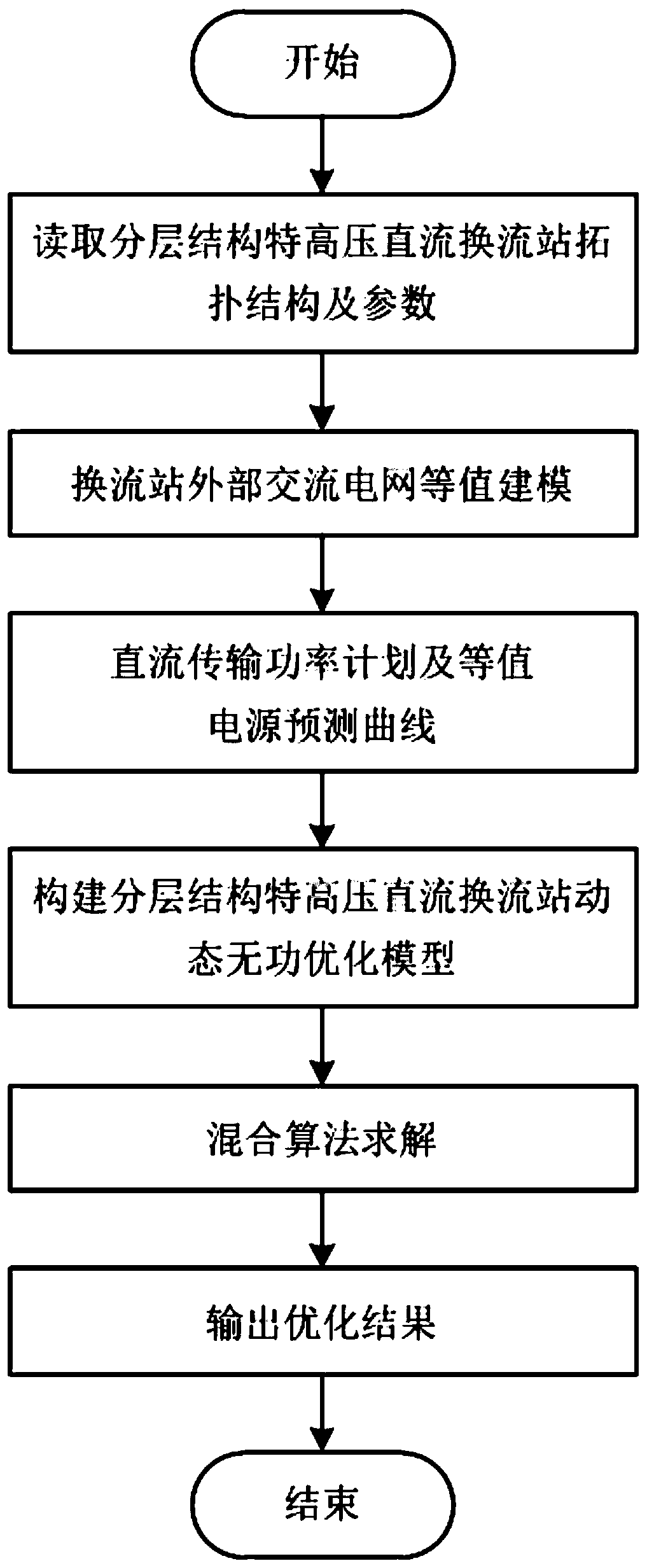
[0087] The coordinated dynamic reactive power optimization method of the condenser and the layered UHVDC receiving end converter station mainly includes the following steps:

[0088] 1) Establish the dynamic reactive power optimization model M of the UHVDC receiving-end converter station with hierarchical structure.

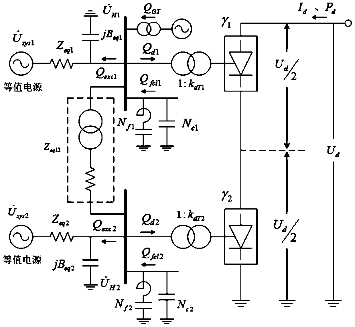
[0089] The AC grid connected to the hierarchical structure UHV DC converter station adopts a multi-power equivalent model, and the subscripts 1 and 2 represent the AC voltage levels of 500kV and 1000kV, respectively. It should be noted that, in order to uniformly represent the following models, it is assumed that the two AC voltage levels are connected to the condenser, but in actual engineering, the condenser is only connected to the 500kV AC grid side.

[0090] The multi-power source equivalent model is used to perform equivalent value on the external AC grid of the converter station, and at the same time, the equivalent susceptance of the external grid on the ...

Embodiment 2

[0162] An experiment to verify the coordinated dynamic reactive power optimization method of the condenser and the hierarchical structure UHV DC receiving end converter station, the main steps are:

[0163] 1) For the receiving end converter station of a layered UHV DC project, dynamic reactive power optimization is carried out based on its typical daily DC transmission power planning curve.

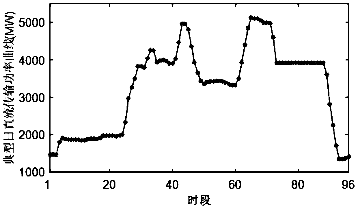
[0164] 2) Select the receiving-end converter station of the UHV DC project with hierarchical structure and its typical daily DC transmission power planning curve, and perform equivalent modeling and equivalent power supply curve prediction for the AC power grid. The typical daily DC transmission power planning curve is as follows: figure 2 As shown, the topological diagram of the hierarchical UHVDC converter station is as follows image 3 shown. image 3 Among them, Zeq is the equivalent impedance, and Beq is the equivalent admittance.

[0165] 3) According to the network structure p...


PUM


Abstract

The invention discloses a coordinated dynamic reactive power optimization method for a phase modifier and a hierarchical-structure UHV DC receiving end converter station. The coordinated dynamic reactive power optimization method comprises the main steps of: 1) establishing a hierarchical-structure UHV DC receiving end converter station dynamic reactive power optimization model M; 2) and calculating the hierarchical-structure UHV DC receiving end converter station dynamic reactive power optimization model M, so as to optimize the hierarchical-structure UHV DC receiving end converter station. The coordinated dynamic reactive power optimization method adopts a hybrid solution algorithm based on a nonlinear interior point method and a dynamic programming method, comprises three sub-problems of global optimization based on the nonlinear interior point method, discrete control variable optimization based on the dynamic programming method and continuous control variable optimization based onthe nonlinear interior point method, and has the advantages of high solution efficiency and stable calculation result.

Description

technical field [0001] The invention relates to the field of converter station optimization, in particular to a coordinated dynamic reactive power optimization method for a converter station and a layered structure ultra-high voltage direct current receiving end converter station. Background technique [0002] With the development of my country's UHVDC transmission technology, multi-circuit DC centralized feeding into the load center of the receiving end has become an important issue restricting the development of my country's power grid. severe challenge. For this reason, Chinese experts and scholars took the lead in proposing a new method of UHV DC layered access to the AC grid to solve the problems caused by DC feed-in from the perspective of the grid structure. The topological structure of the DC converter station system in the layered access mode is more complicated. In addition to the AC and DC systems, there are electrical coupling relationships between the high-end a...

Claims


Application Information

Patent Timeline
Patent Type & Authority Applications(China)
IPC IPC(8): H02J3/18H02J3/36
CPCY02E40/30Y02E60/60
Inventor 莫静山颜伟田其生钱威饶渝泽
Owner CHONGQING UNIV
Learn More