
Thread break detection device for thread guide tubes

A technology for wire breakage detection and wire passage, which is used in textiles, textiles, papermaking, looms, etc., can solve the problems that the rotating sheet cannot be completely reset, affecting production efficiency, and low production efficiency, and achieves long service life and production efficiency. High, timely alarm effect

Pending Publication Date: 2019-06-04
YIWU WEIKEN ELECTRONICS TECH CO LTD
View PDF11 Cites 0 Cited by
  • Summary
  • Abstract
  • Description
  • Claims
  • Application Information

AI Technical Summary

Problems solved by technology

[0002] At present, the thread breakage detectors of common looms on the market are usually fixed with wire slots at the upper and lower ends of one side of the main body, and a rotating piece is directly rotated in the main body. Torsion spring, one side of the rotating shaft is fixed with a stop rod, and the rotation path of the stop rod passes through the straight line between the upper and lower wire slots; by turning the stop rod to a position close to the side of the main body, the stop rod will be under the action of the torsion spring The spring back will be blocked by the yarn between the upper and lower slots during the rebound, so that the rotating piece cannot be completely reset; The contact sensor in the main body is in contact, and the disconnection detection operation is completed through the signal of the contact sensor; however, the elastic force on the torsion spring will increase with the increase of the rotation distance, and the gap between the upper and lower ends of the wire slot If the distance between them is large, the resilience of the stop bar will easily stretch the yarn, resulting in false alarms and affecting production efficiency; and when the tension of the yarn is large, the resilience of the stop bar will easily tear the yarn, affecting Production efficiency; at the same time, if the torsion spring is in a torsion state for a long time, the torsion spring or the position where the torsion spring is fixedly connected to the main body is easily damaged, which makes the service life of the equipment shorter
Therefore, existing wire breakage detectors have the problem of low production efficiency or short service life

Method used


Image

  • Thread break detection device for thread guide tubes
  • Thread break detection device for thread guide tubes
  • Thread break detection device for thread guide tubes

Examples


Embodiment Construction

[0018] The present invention will be further described below in conjunction with the accompanying drawings and embodiments, but not as a basis for limiting the present invention.

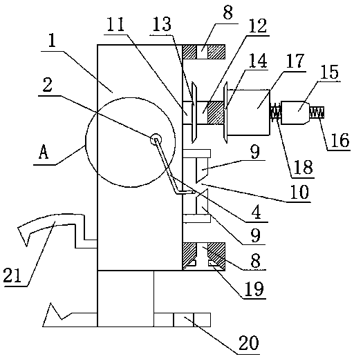
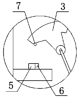
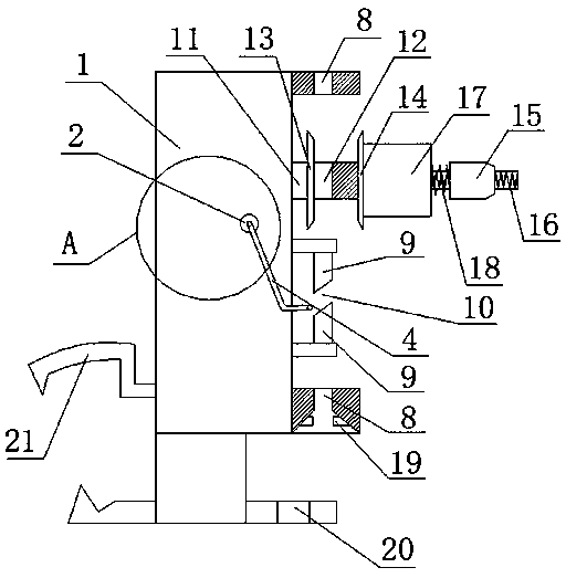
[0019] Example. A disconnection detection device for a line pipe, which is composed of figure 1 and 2 As shown, it includes a main body 1, and a rotating shaft 2 is installed in the main body 1; a rotating block 3 is fixed on one side of the rotating shaft 2, and a stop rod 4 is fixedly connected to the other side of the rotating shaft 2; Hall sensor 5 on the rotation path of 3, a magnet 6 is fixedly connected to one side of the Hall sensor 5; a metal block 7 is fixed at a position corresponding to the magnet 6 on the rotating block 3.

[0020] The mass of the rotating block 3 is equal to the quality of the stop bar 4; the upper and lower ends of the main body 1 on one side of the stop bar 4 are connected with wire slots 8, and the position between the two wire slots 2 is set There are two wire p...


PUM


Abstract

The invention discloses a thread break detection device for thread guide tubes, which comprises a body (1). A rotary shaft (2) is rotationally arranged in the body (1); a rotary block (3) is fixed toone side of the rotary shaft (2); a retaining bar (4) is fixedly connected to the other side of the rotary shaft (2); a hall sensor (5) on a rotational path of the rotary block (3) is arranged in theb body (1); a magnet (6) is fixedly connected to one side of the hall sensor (5); a metal block (7) is fixed to the part, corresponding to the magnet (6), of the rotary block (3). The thread break detection device has the advantages of improved production efficiency, long service life and good mounting convenience.

Description

technical field [0001] The invention relates to a wire break detector, in particular to a wire break detection device for a line pipe. Background technique [0002] At present, the thread breakage detectors of common looms on the market are usually fixed with wire slots at the upper and lower ends of one side of the main body, and a rotating piece is directly rotated in the main body. Torsion spring, one side of the rotating shaft is fixed with a stop rod, and the rotation path of the stop rod passes through the straight line between the upper and lower wire slots; by turning the stop rod to a position close to the side of the main body, the stop rod will be under the action of the torsion spring The spring back will be blocked by the yarn between the upper and lower slots during the rebound, so that the rotating piece cannot be completely reset; The contact sensor in the main body is in contact, and the disconnection detection operation is completed through the signal of t...

Claims


Application Information

Patent Timeline
Patent Type & Authority Applications(China)
IPC IPC(8): D03D51/18
Inventor 安永苍王建光娄国华
Owner YIWU WEIKEN ELECTRONICS TECH CO LTD
Learn More