Engine room heat shield and automobile

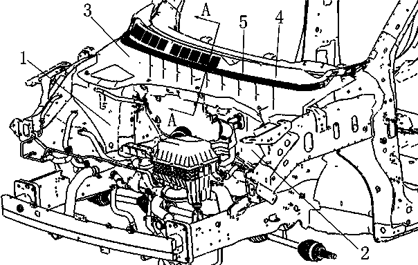
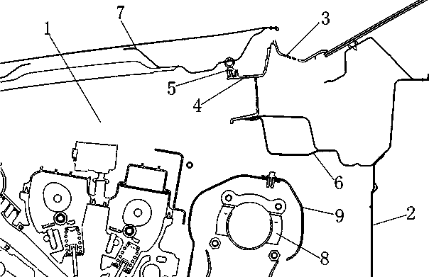
A technology for heat shields and cabins, which is applied to vehicle components, transportation and packaging, superstructure sub-assemblies, etc., can solve the problems of reducing the service life of the rear sealing strip 5 of the front cover and the wiper trim 3, so as to reduce heat damage, slowing down the rate of aging

Active Publication Date: 2019-06-04
CHONGQING CHANGAN AUTOMOBILE CO LTD
View PDF7 Cites 2 Cited by
  • Summary
  • Abstract
  • Description
  • Claims
  • Application Information

AI Technical Summary

Problems solved by technology

When the car stops, the high-temperature air emitted by the turbocharger 8 will spread upwards, and the high-temperature air will flow to the overlapping position of the front cover assembly 7 and the front cover rear sealing strip 5 and slowly accumulate and then spread downwards, which causes the front cover The rear sealing strip 5 and the wiper trim 3 are soaked in high-temperature air for a long time. Since the rear sealing strip 5 of the front cover is made of rubber, and the wiper trim 3 is made of plastic, soaking in high-temperature air for a long time will accelerate the rear of the front cover. The aging of the sealing strip 5 and the wiper trim 3 reduces the service life of the front cover rear sealing strip 5 and the wiper trim 3

Method used


Image

  • Engine room heat shield and automobile
  • Engine room heat shield and automobile
  • Engine room heat shield and automobile

Examples


Embodiment Construction

[0024] The present invention will be further described below in conjunction with accompanying drawing.

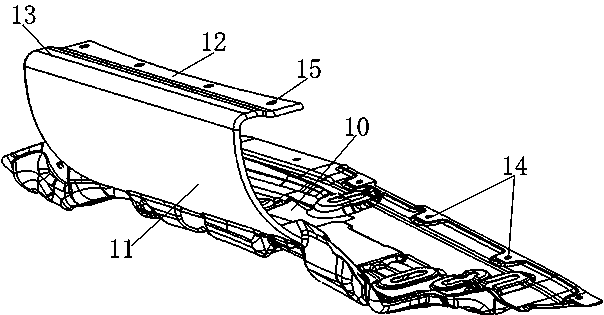
[0025] like image 3 and Figure 4 The cabin heat shield shown includes a bottom plate portion 10 connected to the rear wall 2 of the engine nacelle 1, a sloping plate portion 11 whose lower edge is connected to the front edge of the bottom plate portion 10, and from the sloping plate portion 11. The upper edge is a flange 12 extending backwards. The flange 12 is used to connect with the sealing strip installation platform 4 on the wiper trim 3 , and the sloping plate portion 11 gradually extends upwards from the rear to the front. With the above-mentioned technical solution, the bottom plate part 10 plays the role of heat insulation, and the sloping plate part 11 plays the role of heat insulation and guiding the high-temperature air; the high-temperature air formed by the turbocharger is guided by the sloping plate part 11 , can reduce the flow of hot air to the front co...


PUM


Abstract

The invention relates to an engine room heat shield and an automobile. The engine room heat shield comprises a bottom plate part used for being connected with the engine room rear wall of an engine room, an inclined plate part with the lower edge connected with the front edge of the bottom plate part, and a flanging extending backwards from the upper edge of the inclined plate part. The flanging is used for being connected with a sealing strip mounting platform on awindscreen wiper decorating part, and the inclined plate part gradually extends upwards from back to front. The engine room heat shield provided by the invention can slow down the aging speed of a front shield rear sealing strip and the windscreen wiper decorating part.

Description

technical field [0001] The invention relates to an automobile engine compartment, in particular to an engine compartment heat shield and an automobile. Background technique [0002] When the turbocharger is working, it will generate high temperature, resulting in high temperature of the air around the turbocharger. The high temperature air will affect the normal use of other parts in the engine compartment. Therefore, models with turbochargers need to alleviate the problem of heat damage . like figure 1 and figure 2 As shown, in the prior art, on the one hand, a supercharger heat shield 9 is arranged on the periphery of the turbocharger 8 to block the diffusion of heat; The air is introduced into the engine compartment 1 to take away the heat, thereby achieving cooling. The heat damage problem of the turbocharger 8 can be alleviated to a certain extent by the above two methods, but in the actual use of the car, it is found that the wiper trim 3 at the rear of the engine...

Claims


Application Information

Patent Timeline
IPC IPC(8): B60R13/08B62D25/08
Inventor 刘正雄
Owner CHONGQING CHANGAN AUTOMOBILE CO LTD
Why Eureka
Try Eureka