a detection cable

A technology for detecting cables and conductors, applied in the direction of insulated cables, cables, circuits, etc., can solve the problems of easy damage to the steel wire armor layer, wear of the steel wire on the outer layer of the cable, and short service life of the load-bearing detection cable, so as to prevent wear and tear. Serious, increase service life, simple effect of anti-interference ability

Active Publication Date: 2020-10-16
TIANCHANG HUILING ELECTRIC APPLIANCE METER FACTORY
View PDF5 Cites 0 Cited by
  • Summary
  • Abstract
  • Description
  • Claims
  • Application Information

AI Technical Summary

Problems solved by technology

[0003] However, the load-bearing detection cables in the prior art still have many disadvantages. Because the cables need to work in very harsh high-temperature, high-pressure and corrosive environments, the steel wire armor of the load-bearing detection cables is easily damaged. In addition, many After the first use, the steel wire on the outer layer of the cable is severely worn, and these conditions lead to a short service life of the load-bearing detection cable

Method used


Image

  • a detection cable
  • a detection cable
  • a detection cable

Examples


Embodiment Construction

[0024] The technical solutions in the embodiments of the present invention will be clearly and completely described below with reference to the accompanying drawings in the embodiments of the present invention. Obviously, the described embodiments are only a part of the embodiments of the present invention, but not all of the embodiments. Based on the embodiments of the present invention, all other embodiments obtained by those of ordinary skill in the art without creative efforts shall fall within the protection scope of the present invention.

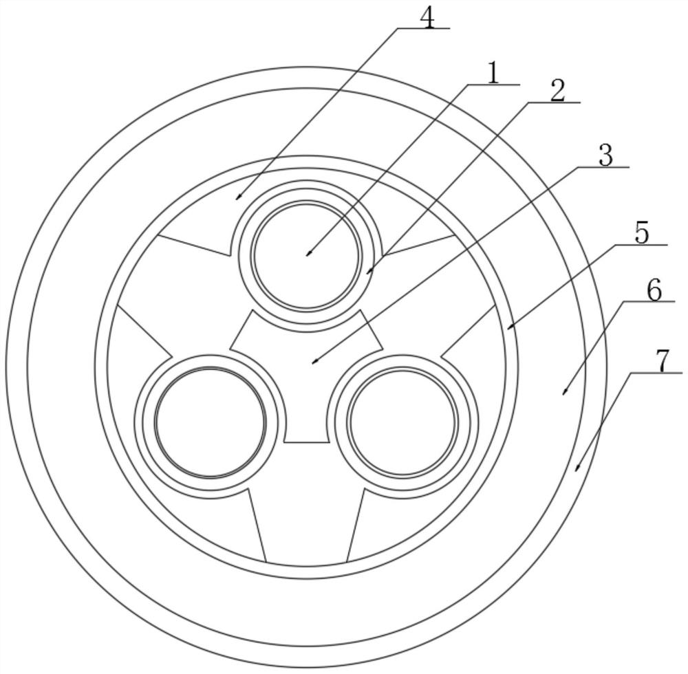
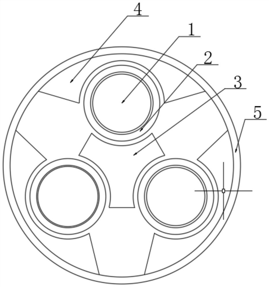
[0025] according to figure 1 , 2 A detection cable shown in and 5 includes a conductor core 1, the surface of the conductor core 1 is fixedly connected with a conductor shielding layer 2, and the surface of the conductor shielding layer 2 is movably connected to a limit block 3 and a positioning block 4, respectively, The surfaces of the limiting block 3 and the positioning block 4 corresponding to the conductor shielding layer 2 are...


PUM


Abstract

The invention discloses a detection cable and in particular relates to the cable field. The detection cable comprises a conductor core, wherein the surface of the conductor core is fixedly connected with a conductor shielding layer; the surface of the conductor shielding layer is movably connected to a stopping block and a positioning block; and the surface of the positioning block is fixedly connected with a fixing layer. The conductor core can be fixed through the stopping block and the positioning block. Thus, the conductor cores in a cable can be prevented from rotating relative to each other and further from causing the cable to fracture and affecting the electrical performance of the cable. A thermal expansion block is expanded by heat and pushes a fire extinguishing ball to make thefire extinguishing ball in a compressed state. When the cable is fired and burns out the fire extinguishing ball, the compressed fire extinguishing ball eject the carbon dioxide to extinguish the fire, thereby achieving a purpose of high temperature resistance. A first reinforcing layer and a second reinforcing layer can protect the steel wire of an outer armored layer against serious wear, thereby prolonging the service life of the cable.

Description

technical field [0001] The present invention relates to the technical field of cables, and more particularly, the present invention relates to a detection cable. Background technique [0002] The load-bearing detection cable mainly refers to the double steel wire armored cable that can withstand the mechanical load (sling hammer plus the weight of the cable) for underground oil exploration, also known as the oil logging cable. Its functions include logging, perforating, coring, etc. . Logging cables are called "eyes of oil workers" in the petroleum industry. Only through them can we know whether the underground is oil or gas, and can measure technical parameters such as well temperature, well pressure and well deviation. [0003] However, the load-bearing detection cable in the prior art still has many shortcomings. Since the cable needs to work in a very harsh high temperature, high pressure and corrosive environment, the steel wire armor layer of the load-bearing detectio...

Claims


Application Information

Patent Timeline
Patent Type & Authority Patents(China)
IPC IPC(8): H01B7/17H01B7/18H01B7/22H01B7/28H01B7/29
Inventor 董吟梅陆秀国杨茂明王友香郭宗亚
Owner TIANCHANG HUILING ELECTRIC APPLIANCE METER FACTORY
Why Eureka
Try Eureka