
Cycloidal gear tooth profile linear modification method, cycloidal gear and speed reducer

A cycloidal gear tooth and cycloidal gear technology, applied in the direction of instruments, components with teeth, belts/chains/gears, etc., can solve the problems of processing, installation errors, thermal expansion and contraction, elastic deformation, etc., to ensure The effect of meshing performance

Active Publication Date: 2019-05-31
HENAN UNIV OF SCI & TECH
View PDF3 Cites 0 Cited by
  • Summary
  • Abstract
  • Description
  • Claims
  • Application Information

AI Technical Summary

Problems solved by technology

However, due to the processing and installation errors of each component in the cycloidal pinwheel planetary transmission system, elastic deformation will occur after being loaded, and at the same time, thermal expansion and contraction will easily occur during use. If the standard cycloidal wheel and pinwheel The meshing of the pin teeth is easy to cause interference and the lubricating oil film cannot be formed between the cycloidal wheel and the pin teeth, resulting in poor lubrication or even jamming

Method used


Image

  • Cycloidal gear tooth profile linear modification method, cycloidal gear and speed reducer
  • Cycloidal gear tooth profile linear modification method, cycloidal gear and speed reducer
  • Cycloidal gear tooth profile linear modification method, cycloidal gear and speed reducer

Examples


Embodiment Construction

[0063] Embodiments of the present invention will be further described below in conjunction with the accompanying drawings.

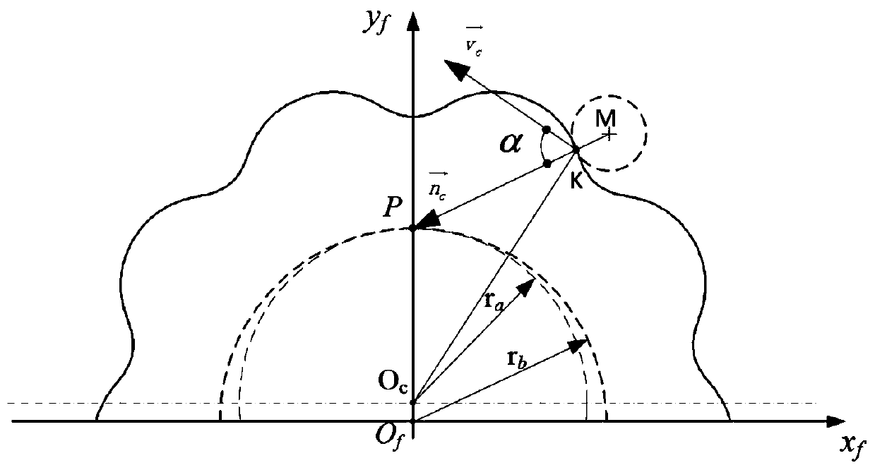
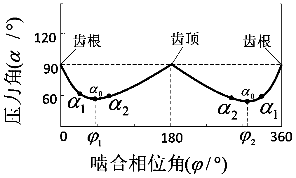
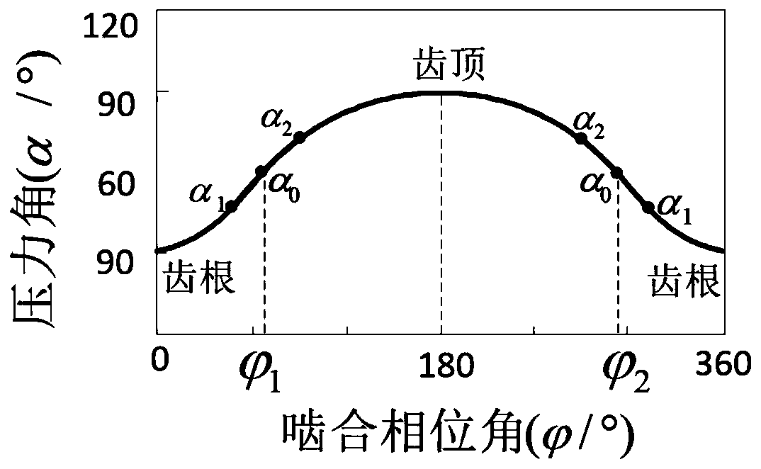
[0064] The specific embodiment of cycloid gear tooth profile straight line method modification method of the present invention, as Figure 1 to Figure 7 As shown, this embodiment takes the optimal force transmission performance as the principle of calculating the modification amount, determines the modification amount of each point in the tooth profile of the cycloid, and subtracts the corresponding modification amount along the normal direction of the corresponding point , get the modified cycloid tooth profile, and carry out the simulation test to adjust the size of the modified amount.

[0065] Specifically include the following steps:

[0066] 1. Determine the distribution law of the pressure angle and the meshing phase angle of the cycloidal gear profile point

[0067] established as figure 1 The schematic diagram of the meshing state of the cycl...


PUM


Abstract

The invention relates to the technical field of cycloidal gear machining, in particular to a cycloidal gear tooth profile linear modification method, a cycloidal gear and a speed reducer. The modification method comprises the following steps: 1) determining a distribution rule between a pressure angle and a meshing phase angle at each point in a cycloidal gear tooth profile; 2) obtaining the modification amount of the minimum pressure angle point, the tooth crest and the tooth root; 3) establishing a first linear equation of the relation between the pressure angle of each tooth profile point in the range from the modification reference point to the tooth top and the modification amount by taking the modification reference point, the pressure angle of the tooth top and the modification amount as two end points; Establishing a second linear equation of the relationship between the pressure angle of each tooth profile point in the range from the modification reference point to the tooth root and the modification amount by taking the pressure angle and the modification amount of the modification reference point and the tooth root as two end points; 4) obtaining the modification amountof each point of the cycloidal gear tooth profile according to the first linear equation, the second linear equation and the distribution rule, and 5) subtracting the corresponding modification amountfrom the normal direction of each tooth profile point of the cycloidal gear to obtain the modified cycloidal gear tooth profile.

Description

technical field [0001] The invention relates to the technical field of cycloidal wheel processing, in particular to a cycloidal wheel tooth profile straight line modification method, a cycloidal wheel and a reducer. Background technique [0002] As an important part of robot transmission, RV reducer has the most direct influence on the transmission accuracy of cycloidal pin wheel planetary transmission. There is no meshing gap in standard cycloidal planetary transmission. However, due to the processing and installation errors of each component in the cycloidal pinwheel planetary transmission system, elastic deformation will occur after being loaded, and at the same time, thermal expansion and contraction will easily occur during use. If the standard cycloidal wheel and pinwheel The meshing of the pin teeth is easy to cause interference and a lubricating oil film cannot be formed between the cycloidal wheel and the pin teeth, resulting in poor lubrication or even jamming. ...

Claims


Application Information

Patent Timeline
IPC IPC(8): G06F17/50F16H55/08
Inventor 李天兴安小涛邓效忠苏建新田蒙邢春荣王国峰
Owner HENAN UNIV OF SCI & TECH
Learn More