
a fish feeding boat

A fish boat and feed technology, which is applied in the fish farming industry, special-purpose ships, rotating propellers, etc., can solve the problems of heavy physical exertion of workers, unbearable physical strength of workers, and differences in fish growth and size, and achieve multi-area feeding, Reduce labor intensity and protect the environment

Active Publication Date: 2021-07-30
山东同其数字技术有限公司
View PDF8 Cites 0 Cited by
  • Summary
  • Abstract
  • Description
  • Claims
  • Application Information

AI Technical Summary

Problems solved by technology

[0002] In fish farms, regular feeding is required for the growth of fish. Now the most common feeding method is to mix and stir various feeds according to the proportion on the shore, usually manually, and then mix the mixed feed. Move it to the power-assisted boat, draw it manually to a certain area, manually scoop the feed, and then throw it in all directions. This method has a large feed projection area and can achieve better simultaneous feeding. However, this method is completely dependent on manpower, which consumes a lot of physical strength for the workers and takes time. For a long time, the physical strength of the workers is unbearable; another way of feeding is that the workers stand on the shore and throw the feed far away with the help of their hands. It reduces physical labor, but in this way, the feed projection is concentrated on the shore, and it is difficult for fish that are far apart to eat the feed. As time goes by, the growth size of fish will vary greatly
Both of these feed projection methods need to be done manually, and it is difficult to automate

Method used


Image

  • a fish feeding boat
  • a fish feeding boat
  • a fish feeding boat

Examples


Embodiment Construction

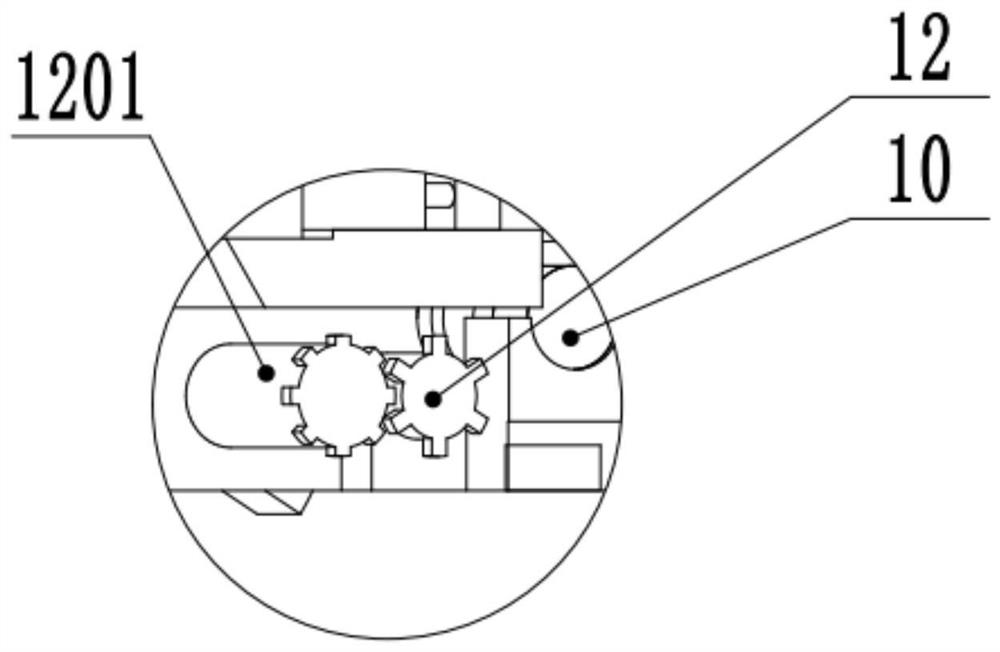
[0015]A fish feeding boat is composed of a first motor 1, a mixing tank 2, a hull shell 3, a propeller 4, a solar panel 5, a storage battery 6, an air pump 7, a controller 8, a feeding control device 9, and a second motor 10 , a feed projection device 11 and a third motor 12, the first motor 1 is installed on the upper surface of the hull 3, and is connected with the stirring shaft 201 through the first belt 101; the stirring barrel 2 Two-thirds is a cylindrical structure, and the remaining one-third is a hemispherical shell structure. The mixing tank 2 has no upper cover, and an upper discharge port 205 is opened at the center of the hemispherical shell 204. The mixing tank 2 Half of the bucket body is located on the upper surface of the hull body 3, and half is located below the upper surface of the hull body 3. There are two parts of stirring blades 202 on the stirring shaft 201. The stirring shaft 201 is connected with the mixing tank 2 through a positioning bracket 203, an...


PUM


Abstract

A fish feeding boat, belonging to the field of fishery, is composed of a first motor, a mixing tank, a hull, a propeller, a solar panel, a storage battery, an air pump, a controller, a feeding control device, a second motor, a feed projection device and a first Composed of three motors, the mixing tank in this invention can hold a variety of feeds or medicines, and the stirring shaft can realize the uniform mixing of feeds and medicines, which greatly reduces the labor intensity of workers; the electromagnet and spring in this invention can realize The left and right movement of the blanking control plate realizes the lowering and stopping of the feed. The rolling body can reduce the friction of the blanking control plate when it moves; the first cylinder moves to compress the feed, and the compressed feed is located in the compressed block hole, and then With the movement of the second cylinder, the compressed feed can be projected far away by means of the movement of the second piston rod, and the compressed feed can expand the projection area, thereby realizing multi-area feeding.

Description

technical field [0001] The invention relates to a fish-feeding boat, specifically a feed control console with a special structure and a feed projection device, and a stirring device capable of stirring feed is installed, which belongs to the field of fishery. Background technique [0002] In fish farms, regular feeding is required for the growth of fish. Now the most common feeding method is to mix and stir various feeds according to the proportion on the shore, usually manually, and then mix the mixed feed. Move it to the power-assisted boat, draw it manually to a certain area, manually scoop the feed, and then throw it in all directions. This method has a large feed projection area and can achieve better simultaneous feeding. However, this method is completely dependent on manpower, which consumes a lot of physical strength for the workers and takes time. For a long time, the physical strength of the workers is unbearable; another way of feeding is that the workers stand o...

Claims


Application Information

Patent Timeline
Patent Type & Authority Patents(China)
IPC IPC(8): A01K61/80B63B35/00B63H1/14B01F7/24
CPCY02A40/81
Inventor 田腾姚志鹏梁化斌
Owner 山东同其数字技术有限公司
Learn More