
Combined type fast-assembling railway counter-rail apparatus

A combination and railway technology, applied in the direction of roads, tracks, rails, etc., can solve the problems of ineffective adjustment, heavy labor, hidden dangers, etc., and achieve the effect of mechanized operation, safe and reliable operation, and reduced labor intensity

Inactive Publication Date: 2009-12-23
杨金福
View PDF5 Cites 0 Cited by
  • Summary
  • Abstract
  • Description
  • Claims
  • Application Information

AI Technical Summary

Problems solved by technology

There are two major problems at present: 1. The distance between the current guard rail device and the main rail is far, and the state cannot be effectively adjusted, nor can it effectively prevent the train wheel from derailing. No longer scroll outward when blocked
Due to the heavy weight and long size of the guard rail, dozens of people are required to work together when disassembling and assembling. The labor is not only heavy, but there are hidden dangers of unsafety at any time.

Method used


Image

  • Combined type fast-assembling railway counter-rail apparatus
  • Combined type fast-assembling railway counter-rail apparatus
  • Combined type fast-assembling railway counter-rail apparatus

Examples


Embodiment Construction

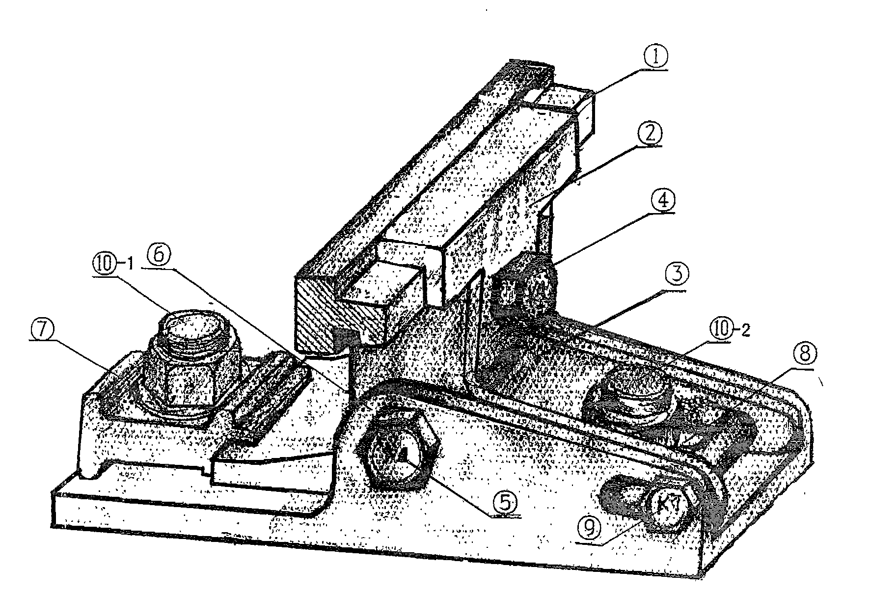
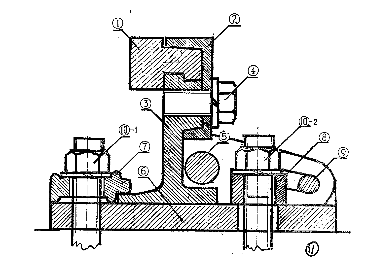
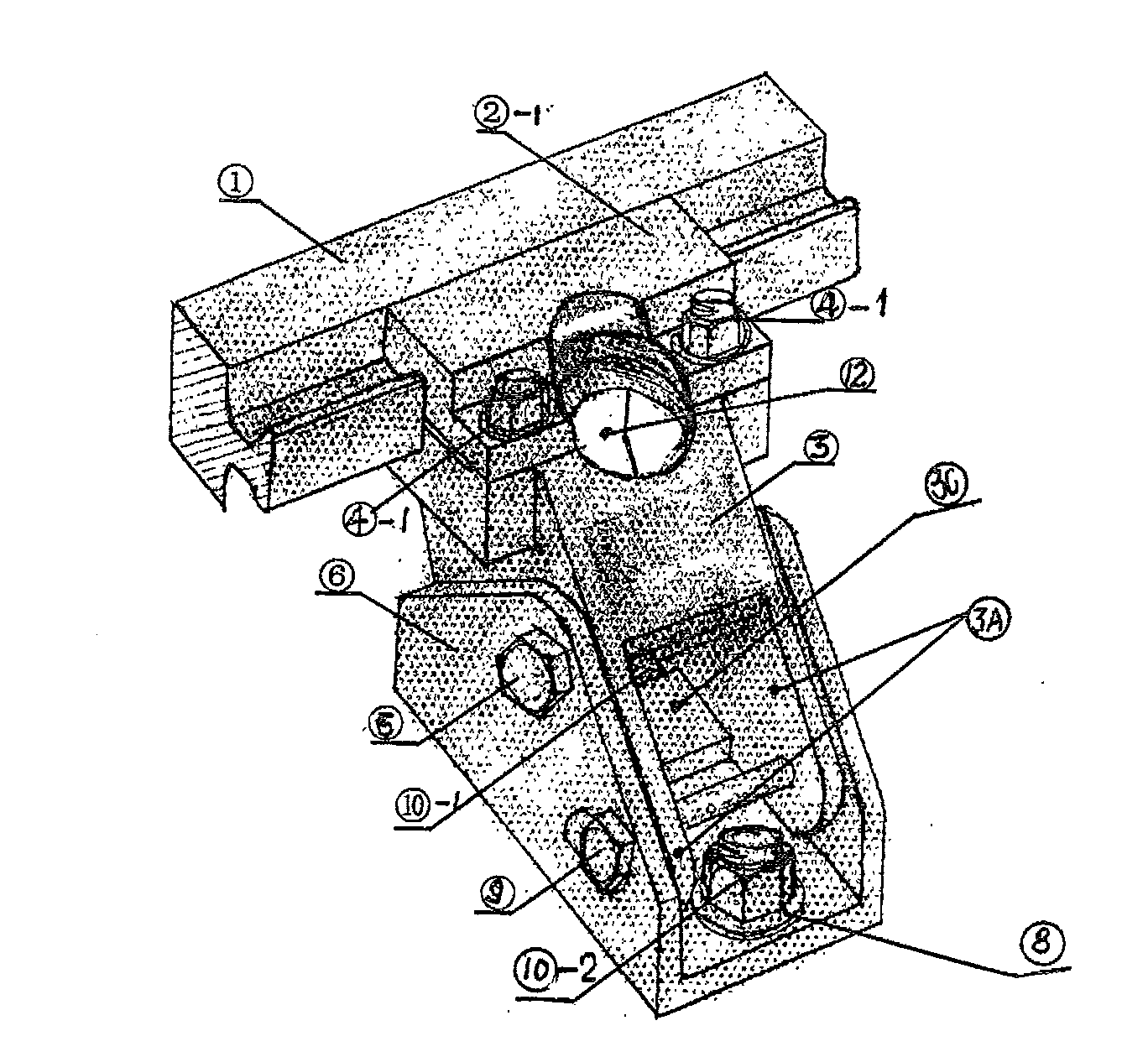
[0013] In combination with the given embodiments, it can be seen that the key design of the present invention includes the guard rail 1 and the positioning mechanism for fixing the guard rail 1 on the sleeper 11 so as to maintain a uniform distance from the side of the main rail. The key design is that the guard rail 1 is positioned on the support 3 with two turning flaps 3A by means of rail clips and positioning bolts. The support 3 can form a position by means of the slotted holes provided on the two turning wing plates 3A or the slotted holes on the slotted side 6A of the slotted base 6, the turning shaft 9 and the bracket base 6 with the slotted side 6A positioned on the sleepers. Adjustable hinge fit. Support 3 and support base 6 are combined into one by means of fixing bolt pin 5, two fixing bolts (10-1, 10-2) linking to each other with sleepers and supporting pressing plates (7, 8), and are fixed on corresponding sleepers 11.

[0014] Tighten the bolt pin 5 and two fix...


PUM


Abstract

The invention relates to an improvement of a guard rail device in the railway rail equipment, which is particularly suitable for an erection of dangerous segments in a rail traffic. The structure of the guard rail device consists of guard rails and a positioning device which is used for fixing the guard rail on a timber so as to lead the guard rail to keep an even distance from a lateral side of a main rail. The key improvement lies in that the guard rail is positioned on a bracket with two turnover wing plates by a rail clamp and a locating bolt; with the assistance of groove-shaped holes and rotating axle of the groove-shaped holes on a groove edge of a groove-shaped base arranged on the two turnover wing plates, the bracket and a bracket base positioned on the timber with groove edges can form a hinge coordination, the position of which can be adjusted. The bracket and the bracket base can be combined with a corollary pressure plate as a whole by a fixed bolt pin and two fixed bolts to be fixed on the corresponding timber.

Description

technical field [0001] The invention relates to a special facility for railway safe operation. Specifically, it is a preventive facility for train derailment, a combined fast-loading railway guard rail device. Background technique [0002] In order to ensure the safe passage of trains in dangerous areas and prevent major accidents caused by derailment, especially for driving safety when passing through curves, slopes, culverts and overhead railway bridges, usually two Two limit protective guard rails are added on the inner side of the rail. The guard rail is fixed on the sleepers by the positioning mechanism to keep a uniform distance from the side of the main rail, and together with the main rail, it can limit and guide the moving wheels. There are two major problems at present: 1. The distance between the current guard rail device and the main rail is far, and the state cannot be effectively adjusted, nor can it effectively prevent the train wheel from derailing. No lon...

Claims


Application Information

Patent Timeline
Patent Type & Authority Patents(China)
IPC IPC(8): E01B5/18
Inventor 杨金福贾国光
Owner 杨金福
Learn More