Photoelectric oscillator for measuring magnetic field and measuring method thereof
A photoelectric oscillator and photodetector technology, applied in the field of microwave photonics technology and sensing measurement, can solve the problems of complex magnetic field measurement demodulation method, poor stability, low sensitivity, etc., to reduce complexity, cost, and stability. The effect of improving and improving the sensitivity
- Summary
- Abstract
- Description
- Claims
- Application Information
AI Technical Summary
Problems solved by technology
Method used
Image


Examples
Embodiment 1
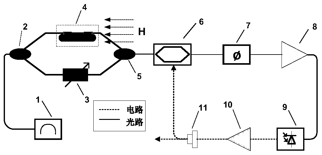
[0047] figure 1 It is a structural schematic diagram of the photoelectric oscillator for measuring the magnetic field of the present embodiment, referring to figure 1 , the device includes: a light source 1, a first optical coupler 2, an adjustable optical delay module 3, an optical fiber sensor head 4 with a magnetostrictive material, a second optical coupler 5, an electro-optic modulator 6, a dispersion element 7. Optical amplifier 8, photodetector 9, microwave amplifier 10 and power divider 11.
[0048] A Mach-Zehnder Interferometer (MZI) is formed between the two optical couplers, and one arm of the MZI includes an optical fiber sensing head 4 with a magnetostrictive material, which is used as the sensing arm, namely It is the optical fiber of the sensor head, wherein the optical fiber can be single-mode optical fiber, few-mode optical fiber, D-type optical fiber or other stress-sensitive optical fiber, which is used to induce the corresponding stretching deformation of t...
Embodiment 2
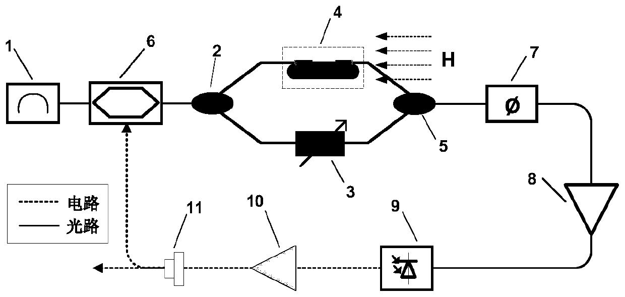
[0063] figure 2 It is a structural schematic diagram of the photoelectric oscillator for measuring the magnetic field of the present embodiment, referring to figure 2 , the device includes: a light source 1, a first optical coupler 2, an adjustable optical delay module 3, an optical fiber sensor head 4 with a magnetostrictive material, a second optical coupler 5, an electro-optic modulator 6, a dispersion element 7. Optical amplifier 8, photodetector 9, microwave amplifier 10 and power divider 11.
[0064] The specific principle and implementation of the photoelectric oscillator-based humidity measurement using the device of this embodiment are similar to the description in the first embodiment above, and will not be repeated here.
[0065] The differences between this embodiment and Embodiment 1 are:
[0066] In this embodiment, the electro-optic modulator 6 is located on one arm of the MZI, and the optical signal output by the light source 1 enters the MZI formed by the ...
Embodiment 3
[0069] This embodiment provides a method for measuring a magnetic field by a photoelectric oscillator, including the following steps:
[0070] 1) After the optical signal sent by the light source is split by the first optical coupler, it is transmitted along the two arms of the MZI, and the length of the two arms is matched by an adjustable optical delay line, and an initial signal is generated when no external magnetic field is applied. The arm length difference is used to generate an initial oscillation frequency, and the second optical coupler combines the optical signals on the two arms of the MZI to cause interference;
[0071]2) The interfering optical signal is modulated by an electro-optical modulator to obtain a modulated signal. The modulated signal is delayed by a dispersive element and amplified by an optical amplifier, then converted into an electrical signal by a photodetector, and then amplified by a microwave amplifier. The power divider is divided into two par...
PUM
 Abstract
Description
Claims
Application Information
 - R&D
- Intellectual Property
- Life Sciences
- Materials
- Tech Scout
- Unparalleled Data Quality
- Higher Quality Content
- 60% Fewer Hallucinations
Browse by: Latest US Patents, China's latest patents, Technical Efficacy Thesaurus, Application Domain, Technology Topic, Popular Technical Reports.
© 2025 PatSnap. All rights reserved.Legal|Privacy policy|Modern Slavery Act Transparency Statement|Sitemap|About US| Contact US: help@patsnap.com