
Combustion chamber and waste incineration boiler for burning waste and working method thereof

A technology of waste incineration and working methods, which is applied in the direction of combustion methods, steam generation methods using heat carriers, and combustion chambers. It can solve the problems of easy corrosion, low reliability, and low incineration efficiency of superheaters, and achieve corrosion prevention, The effect of ensuring reliability and improving efficiency

Active Publication Date: 2020-07-14
广东省特种设备检测研究院惠州检测院
View PDF7 Cites 0 Cited by
  • Summary
  • Abstract
  • Description
  • Claims
  • Application Information

AI Technical Summary

Problems solved by technology

[0004] Aiming at the defects of easy corrosion, low reliability and low incineration efficiency of the superheater in the existing boiler combustion chamber, the present invention provides a combustion chamber and a waste incineration boiler that can prevent corrosion of the superheater, high reliability and high incineration efficiency. its working method

Method used


Image

  • Combustion chamber and waste incineration boiler for burning waste and working method thereof
  • Combustion chamber and waste incineration boiler for burning waste and working method thereof
  • Combustion chamber and waste incineration boiler for burning waste and working method thereof

Examples


Embodiment 1

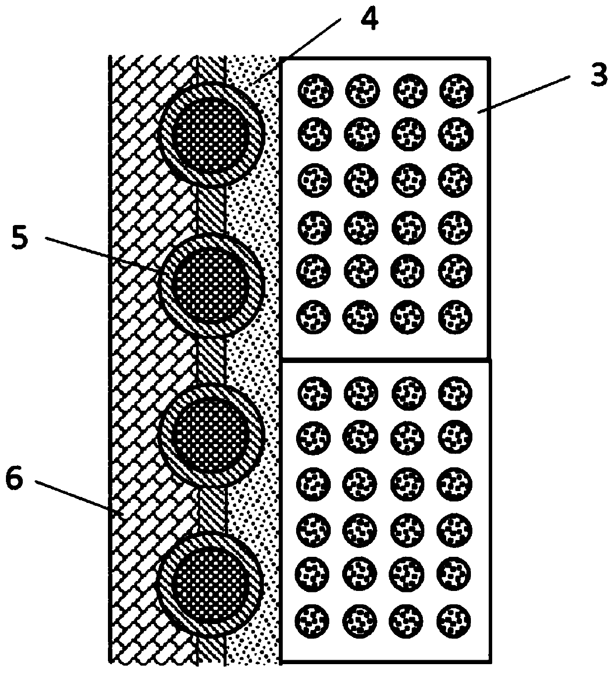
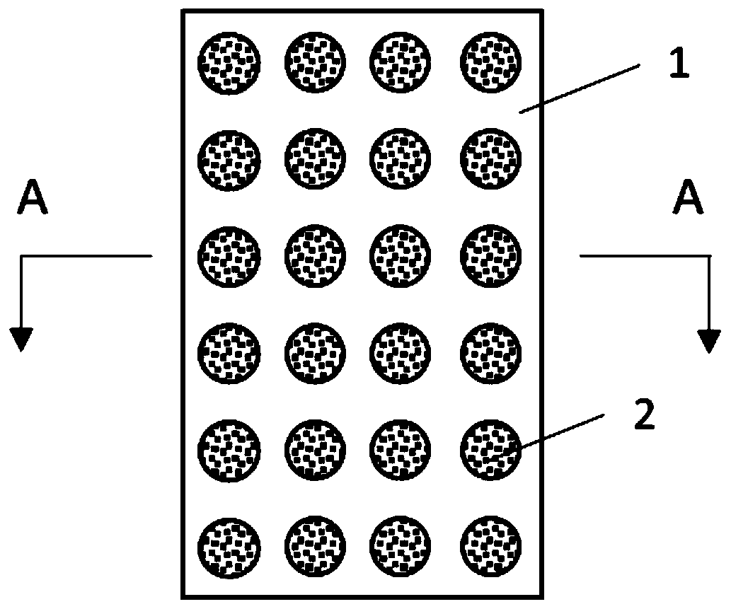
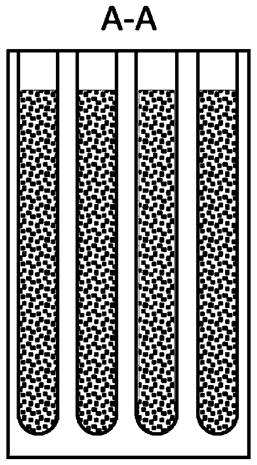
[0023] to combine figure 1 Describe this embodiment. In this embodiment, the present invention relates to a combustion chamber for incinerating garbage. The combustion chamber is composed of phase-change energy storage refractory bricks 3, mortar 4 and exterior walls 6 from inside to outside. The heat exchange tube 5 is horizontally arranged at the junction of the outer wall 6 and the mortar 4, and the mortar 4 is used to bond the phase change energy storage refractory brick 3, the heat exchange tube 5 and the outer wall 6 together. A plurality of deep holes are opened on the energy storage refractory brick 3 , and the phase change material 2 is filled in the deep holes, and the phase change energy storage refractory brick 3 is made of ceramic material 1 .

[0024] More specifically: the phase change material 2 is metal aluminum, aluminum-silicon mixture, aluminum-silicon-copper mixture, aluminum-silicon-magnesium mixture, aluminum-silicon-zinc mixture or aluminum-magnesium-zi...


PUM


Abstract

The invention discloses a combustion chamber used for garbage incineration, a garbage incineration boiler and a working method of the garbage incineration boiler, belongs to a garbage incineration device and a working method thereof, and provides a combustion chamber capable of preventing superheater corrosion, high in reliability and high in incineration efficiency, a garbage incineration boilerand a working method of the garbage incineration boiler. The combustion chamber is formed by bonding phase-change energy storage refractory bricks, mortar and an outer wall from inside to outside; heat exchange pipes are arranged at the combined position of the outer wall of the mortar; the combustion chamber is divided into an upper part and a lower part, a hearth evaporation heated face is located on the upper part of the combustion chamber, a second-stage superheater is located on the lower part of the combustion chamber, and a first evaporation heated face, a first-stage superheater, a second evaporation heated face and a coal economizer are arranged in a flue gas channel from top to bottom; and a boiler barrel is connected with the hearth evaporation heated face, the first evaporationheated face, the second evaporation heated face, the first-stage superheater, the second-stage superheater, a steam turbine, a condenser, a degassing device and the coal economizer. The combustion chamber is mainly used for garbage incineration.

Description

technical field [0001] The invention belongs to a garbage incineration device and its working method, in particular to a combustion chamber for burning garbage, a garbage incineration boiler and its working method. Background technique [0002] At present, the steam parameters used by common waste incineration boilers are generally medium-temperature and medium-pressure conditions (4.0MPa, 400°C), which are caused by the fuel characteristics of waste incineration boilers; incineration of waste at high temperatures will produce corrosive gases, and Acting on the surface of the superheater tube, further increasing the steam parameters will cause corrosion of the superheater tube. The current method is mainly to install anti-corrosion materials on the surface of the superheater, but this method will reduce the reliability of the superheater and need to increase maintenance time , and to improve the efficiency of the waste incineration boiler, the most important point is to incr...

Claims


Application Information

Patent Timeline
Patent Type & Authority Patents(China)
IPC IPC(8): F23G5/00F23G5/44F23G5/46F23M5/02F22B1/02F22B31/00F22D1/02F22D11/06F22G7/12
Inventor 吴海泓杨旭欧阳小平袁寅强向南宏林建明
Owner 广东省特种设备检测研究院惠州检测院
Learn More