


Quick Research
Generate reliable direction feasibility study reports for your R&D in just a few steps.

Technical Q&A
Discover and master advanced knowledge NOW. Basics, ideas, possibilities, all at once.

Find Solutions
As an expert in R&D theories, this can generate solutions to your technical problems instantly.

Evaluate Feasibility
Analyze your overall solution with one click, know your potential R&D risks in advance.

Monitor Landscape
Get weekly tech updates, stay abreast of the latest tech innovations and key insights.
Flame cutting knife
A flame and ignition device technology, applied in the field of cutting tools and supplies, can solve problems such as inconvenience, and achieve the effects of convenient use, simple structure and low production cost
- Summary
- Abstract
- Description
- Claims
- Application Information
AI Technical Summary
Problems solved by technology
Method used
Image

Examples
Embodiment Construction
[0009] The present invention will be further described below in conjunction with the accompanying drawings.
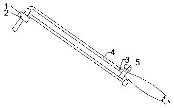
[0010] like figure 1 As shown, the flame cutter of the present invention includes a body 1, an acetylene tube 4 is arranged on the body 1, and an inductor 3 is arranged on the inner wall of the acetylene tube 4, and a point is arranged at the outlet of the body 1. The ignition device 2 is electrically connected to the sensor 3 . It should be understood by those skilled in the art that the device is provided with an inductor 3 in the acetylene tube 4 and an ignition device 2 electrically connected to the sensor 3 at the outlet of the main body 1, so that once it is detected that there is gas in the acetylene tube 4 flow, then the ignition device 2 can be triggered immediately to work, thereby realizing automatic ignition.
[0011] Wherein, an on-off valve 5 is arranged on the acetylene tube 4 in the above-mentioned device, and the inductor 3 is arranged at the outlet ...
PUM
 Abstract
Description
Claims
Application Information
 - R&D Engineer
- R&D Manager
- IP Professional
- Industry Leading Data Capabilities
- Powerful AI technology
- Patent DNA Extraction
Browse by: Latest US Patents, China's latest patents, Technical Efficacy Thesaurus, Application Domain, Technology Topic, Popular Technical Reports.
© 2024 PatSnap. All rights reserved.Legal|Privacy policy|Modern Slavery Act Transparency Statement|Sitemap|About US| Contact US: help@patsnap.com