
Micro LED display panel and preparation method thereof

A display panel and backplane technology, which is applied in semiconductor/solid-state device manufacturing, instruments, electrical components, etc., can solve problems such as abnormal display and influence, and achieve the effects of avoiding being affected, avoiding damage, and avoiding abnormal display

Active Publication Date: 2019-05-24
BOE TECH GRP CO LTD
View PDF5 Cites 16 Cited by
  • Summary
  • Abstract
  • Description
  • Claims
  • Application Information

AI Technical Summary

Problems solved by technology

In the current existing technology, some companies have begun the development of a new generation of display technology. In the existing display technology, the glass substrate preparation process and structure using Micro LED technology is also a research and development project in this field. However, Micro LED display devices are used as The new display shows that during the Micro LED soldering process, the prominent process feature is that the solder paste needs to be attached to the backplane first, and then the Micro LED is pressed and welded to the backplane. TFT characteristics have a certain impact, resulting in abnormal display

Method used


Image

  • Micro LED display panel and preparation method thereof
  • Micro LED display panel and preparation method thereof
  • Micro LED display panel and preparation method thereof

Examples


Embodiment Construction

[0033] The following will clearly and completely describe the technical solutions in the embodiments of the present invention with reference to the accompanying drawings in the embodiments of the present invention. Obviously, the described embodiments are only some, not all, embodiments of the present invention. Based on the embodiments of the present invention, all other embodiments obtained by persons of ordinary skill in the art without making creative efforts belong to the protection scope of the present invention.

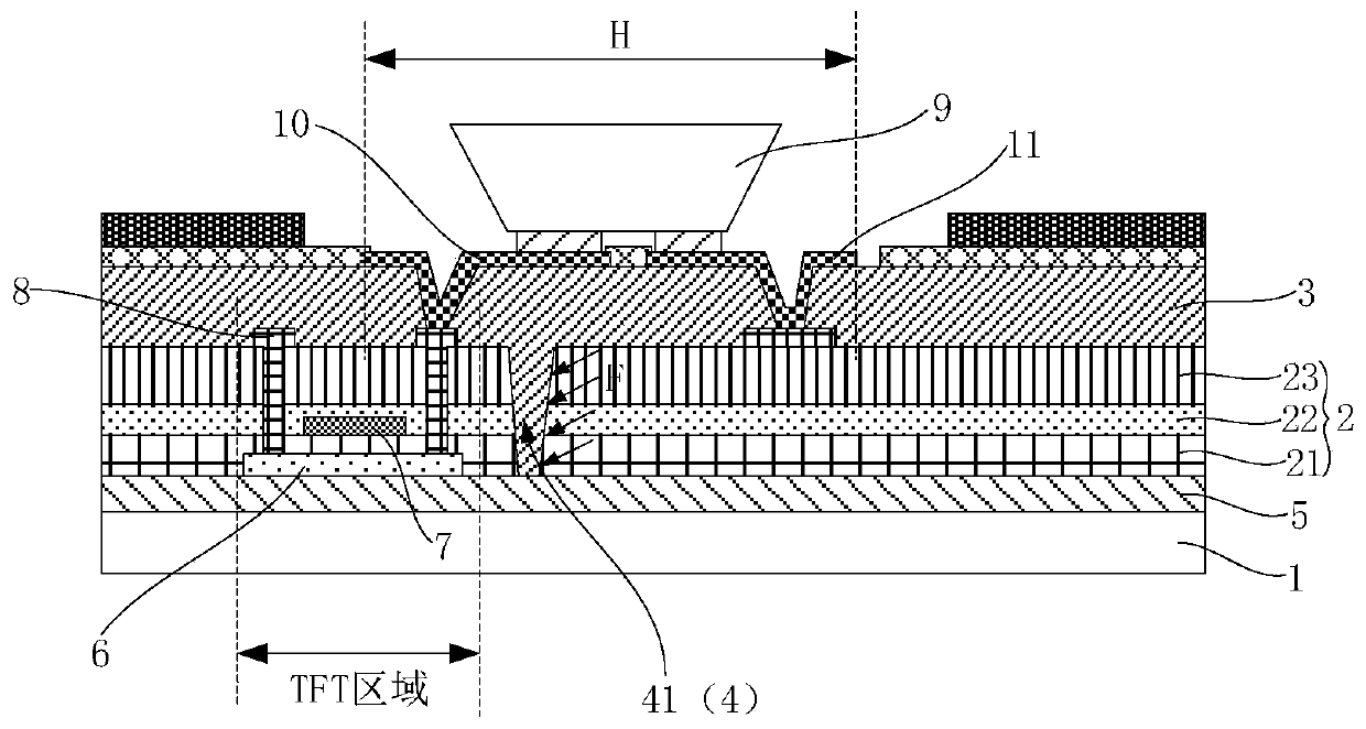
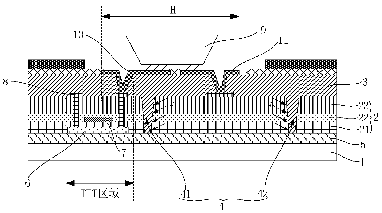
[0034] Please refer to figure 2 and image 3 As shown, a micro-LED display panel provided by an embodiment of the present invention includes a TFT backplane and micro-LEDs 9 fixed on the TFT backplane. The insulating layer 2 and the second insulating layer 3; wherein, the first insulating layer 2 has a groove 24, and the second insulating layer 3 is filled in the groove 24, and the groove 24 is positively projected on the substrate 1 and the TFT backplane T...


PUM


Abstract

The present invention relates to the technical field of display and discloses a micro LED display panel and a preparation method thereof. The micro LED display panel comprises a TFT backplane and a micro LED fixed to the TFT backplane. The TFT backplane includes a substrate and a group including a first insulating layer and a second insulating layer which are successively stacked on the substrate.The first insulating layer has a groove filled with the second insulating layer. The orthographic projection of the groove on the substrate and the orthographic projection of a TFT region in the TFTbackplane on the substrate do not overlap each other. The hardness of the second insulating layer is less than the hardness of the first insulating layer. In the micro LED display panel, the groove inthe first insulating layer of the TFT backplane and the second insulating layer filling the groove constitute a stress relief structure which may a stress relief effect when corresponding deformationoccurs in the micro LED pressure soldering process, thereby avoiding influences on TFT characteristics and avoiding display anomalies.

Description

technical field [0001] The invention relates to the field of display technology, in particular to a micro LED display panel and a preparation method thereof. Background technique [0002] Micro LED (micro LED) is a new generation of display technology, which has higher brightness, better luminous effect and lower power consumption than the existing OLED technology. In the current existing technology, some companies have begun the development of a new generation of display technology. In the existing display technology, the glass substrate preparation process and structure using Micro LED technology is also a research and development project in this field. However, Micro LED display devices are used as The new display shows that during the Micro LED soldering process, the prominent process feature is that the solder paste needs to be attached to the backplane first, and then the Micro LED is pressed and welded to the backplane. TFT characteristics have a certain impact, resu...

Claims


Application Information

Patent Timeline
Patent Type & Authority Applications(China)
IPC IPC(8): H01L27/12H01L23/00H01L21/84G09F9/33
CPCH01L25/167H01L25/0753H01L33/62H01L27/1248H01L27/124H01L27/1259
Inventor 李海旭曹占锋王珂
Owner BOE TECH GRP CO LTD
Learn More