
Mask plate and preparation method thereof

A mask plate and mask plate technology, which is applied in the field of communication, can solve the problems of large size, poor pattern film thickness uniformity, and large film pattern size, so as to reduce the area with insufficient exposure energy, realize refined structure, and enhance The effect of degree of curing

Active Publication Date: 2019-05-24
HEFEI XINSHENG OPTOELECTRONICS TECH CO LTD +1
View PDF7 Cites 1 Cited by
  • Summary
  • Abstract
  • Description
  • Claims
  • Application Information

AI Technical Summary

Problems solved by technology

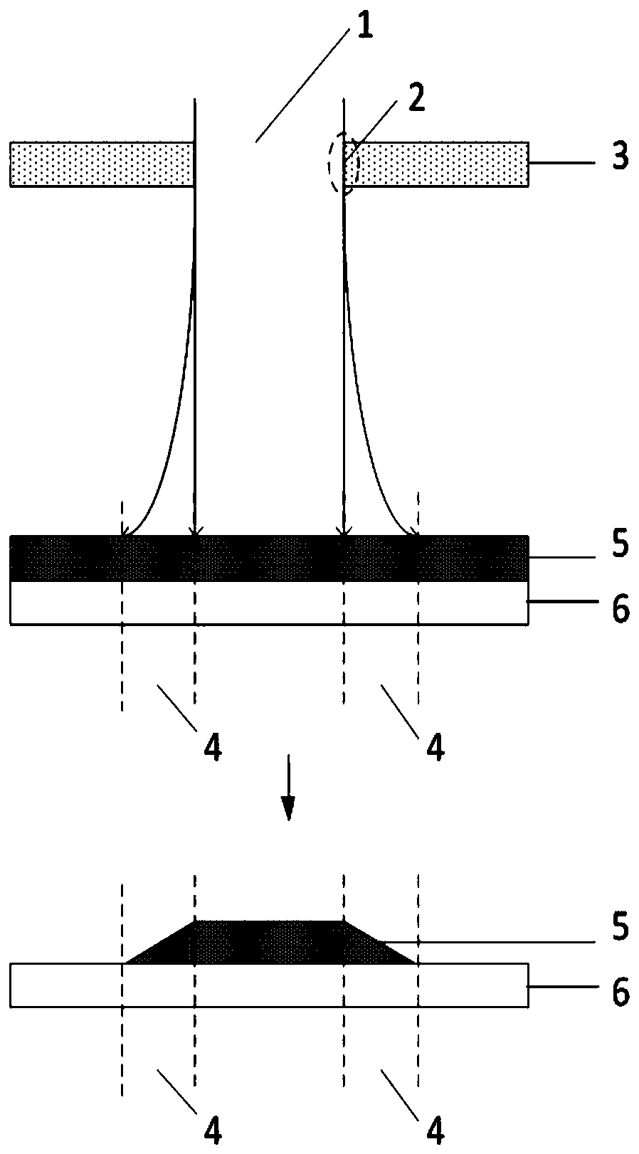
That is, due to the diffraction of light, the spot area that actually passes through the opening of the mask plate to reach the film layer to be exposed is larger, and the pattern size of the final formed color filter is larger than the size of the mask opening area 1, which is not conducive to the fineness of the pattern. It is not conducive to achieving high pixel density (Pixels Per Inch, PPI)
and, if figure 1 As shown, on the other hand, the actual energy of the diffracted part of the light is smaller than that of other areas, which leads to insufficient curing of the edge of the formed color filter pattern, forming a taper angle, and due to the large area of ​​the formed gray area, the taper angle The angle of the color film is small, resulting in poor film thickness uniformity of the pattern of the color film, which will affect the color saturation and contrast of the product
To sum up, using the mask plate in the prior art forms a large gray area in the exposure process, resulting in a large pattern size of the formed film layer and poor film thickness uniformity, which is not conducive to improving the PPI of the display product and affecting product performance.

Method used


Image

  • Mask plate and preparation method thereof
  • Mask plate and preparation method thereof
  • Mask plate and preparation method thereof

Examples


Embodiment Construction

[0042] The embodiment of the present application provides a mask plate, such as figure 2 As shown, at least one opening area 1 is included, and the side 2 of the opening area 1 is a slope with a set angle with the upper surface 7 of the mask plate 3; and at least the tangent 9 between the first part 8 of the slope and the The included angle 10 of the upper surface is greater than 90°, so that the light 11 incident from the upper surface 7 of the mask 3 passes through the reflection of the first part 8 to produce a component parallel to the direction of the plane where the mask 3 is located 12. That is, the light incident from the upper surface of the mask plate is reflected to the opening area through the first part.

[0043] In the mask plate provided by the embodiment of the present application, since the side of the opening area is an inclined plane with a set angle with the upper surface of the mask plate, and the inclined plane has a first angle at which the tangent lin...


PUM


Abstract

The present invention discloses a mask plate and a preparation method thereof. The invention aims to decrease the area of a gray region formed by exposure. The mask plate provided by the embodiments of the present invention comprises at least one opening region; the side surface of the opening region is a slope forming a set include angle with the upper surface of the mask plate; and an included angle between a tangent at least located at the first portion of the slope and the upper surface is greater than 90 degrees, so that light which enters through the upper surface of the mask plate and is reflected through the first portion can generate a component parallel to a plane where the mask plate is located.

Description

technical field [0001] The present application relates to the field of communication technology, and in particular to a mask and a preparation method thereof. Background technique [0002] Currently, the structure of a liquid crystal display panel mainly includes a thin film transistor (TFT) array substrate (Array), a color filter or color filter substrate (CF), and a liquid crystal layer (LC) arranged between the two substrates. The color film substrate includes: black matrix, color film, flat layer and support column processes, except for the flat layer, all of which need to be exposed. The current mainstream use of color filters is the proximity exposure machine, which requires the use of a photomask. The gap between the photomask and the substrate is usually 100-400 microns (um). Taking the formation of color film as an example, the Mask structure used in the prior art is as follows figure 1 As shown, the side 2 of the Mask opening area 1 is a plane perpendicular to th...

Claims


Application Information

Patent Timeline
IPC IPC(8): G03F1/00G03F1/68
Inventor 钟国强袁慧芳尹海斌吉强苏醒
Owner HEFEI XINSHENG OPTOELECTRONICS TECH CO LTD
Learn More